Topic: DMD0453

Module Configuration for BX-HSIOx High Speed I/O Modules
When a BRX CPU powers up and detects a new BX-HSIO1 or BX-HSIO2 module it will automatically create a new module configuration for that module. There is no default configuration for the high-speed inputs and output functions of the HSIO modules; in it's default configuration it has 8 discrete inputs and 8 discrete outputs that operate as simple discrete inputs and outputs mapped into X and Y memory respectively.
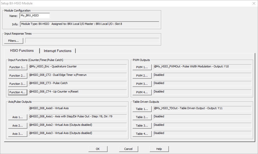
Clicking the Edit Config button in the Module Configuration utility will open the following dialog where the default configuration can be changed by assigning one or more of the modules inputs and outputs to the different functions the module can perform.
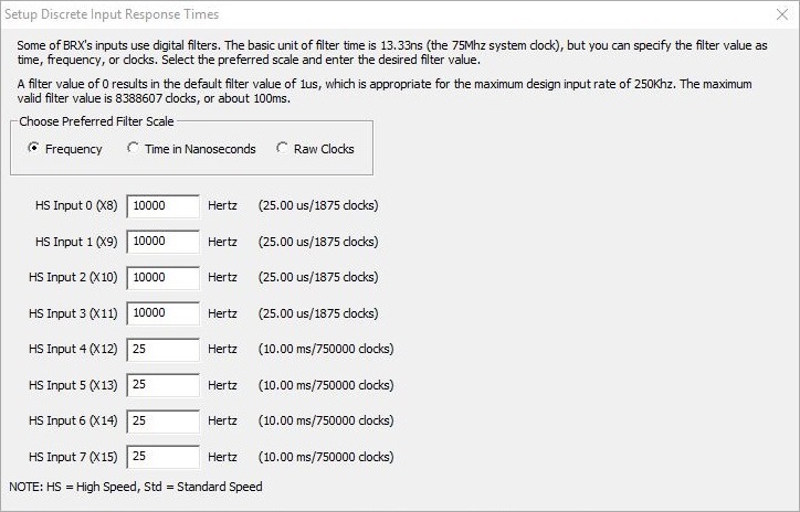
Filters...
BX-HSIO modules can be configured to use digital filtering on inputs that are operating in electrically noisy environments to remove both "false positives" and "false negatives". They do this by requiring that the input signal for a discrete input must remain above or below the input's hardware threshold level longer than the filter time before the module will see the state change. Once the state change is recognized, it must remain at the opposite level longer than the filter time before the module will see the opposite state. A full discussion of how to configure and use these digital filters can be found at BRX Input Filters.
HSIO Functions
Input Functions (Counter / Timer / Pulse Catch)
The BX-HSIO module's inputs can be selected for use as high speed Counters that will count input pulses up to 250kHz, or as high speed Timers that will measure the amount of time between successive input pulses at frequencies up to 250 kHz, or generate an output signal that can be seen by the PLC scan in response to input pulses that are too fast to reliably be seen otherwise (Pulse Catch).
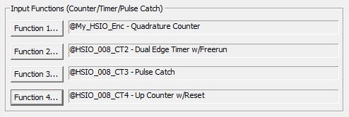
Function 1... / Function 2... / Function 3... / Function 4...: a BX-HSIO module can have up to three Counter / Timer functions defined. Clicking one of theses buttons will open a dialog where Counter or Timer function is selected, the function is given a name, and the number of physical inputs required by that function are selected. A full discussion of how to configure and use these functions can be found at BRX Timer / Counter Functions.
Axis / Pulse Outputs
The BX-HSIO module's outputs can be selected for use as pulse outputs which are typically used to send pulse trains to stepper motors or servo motors at a frequency up to 250 kHz.
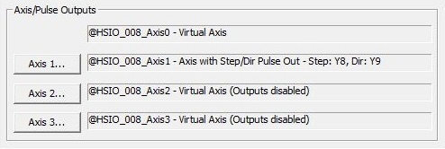
A BX-HSIO module can have up to four Axes. Axis 0 is always virtual, meaning it can be used in the program like the other Axes but can never be used to drive physical outputs.
Axis 1... / Axis 2... / Axis 3... - Axis 1, Axis 2 and Axis 3 can remain virtual or be used to drive physical outputs. Clicking one of theses buttons will open a dialog where the Axis is given a name, the type of outputs required by that Axis, and which physical outputs will be used by that Axis. A full discussion of the BRX Axis and how it uses the pulse outputs can be found at BRX Axis / Pulse Outputs.
Once the outputs for an Axis are selected you will use the following instructions to set the runtime configuration of the Axis and to make the Axis move:
AXSETPROP - Axis Set Properties
AXRSTFAULT - Reset Axis Limit Fault
AXSCRIPT - Run a Sequence of Axis Commands
AXHOME - Axis Perform Home Search
AXPOSSCRV - Axis Move to Position Using S-Curve
AXPOSTRAP - Axis Move to Position Using Trapezoid
AXVEL - Axis Set Velocity Mode
AXGEAR - Axis Electronic Gearing
AXFOLLOW - Axis Position Following with Offset
PWM (Pulse Width Modulated) Outputs
The BX-HSIO module's outputs can be selected for use as a pulse width modulated output which will generate a carrier frequency then vary the width of the pulses that are generated at that frequency.
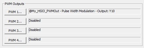
PWM 1... / PWM 2... / PWM 3... / PWM4... : a BX-HSIO module can have up to 4 PWM Outputs. Clicking one of these buttons will open a dialog where the PWM Output is given an name and the physical output that will be used by that PWM is selected. A full discussion of how to select and use these outputs can be found at BRX Pulse Width Modulated Outputs.
Each time a PWM Output is created an associated structure is automatically created. The runtime configuration of the PWM Output is configured by writing to those structure members. As of Do-more Designer v2.5, the PWMOUT - Pulse Width Modulated Output instruction can be used to control a BRX PWM Output instead of manually populating the structure fields.
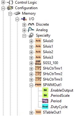
Table Driven Outputs
The BX-HSIO module's outputs can be selected to use the count values of one of the module's High-Speed inputs along with tables of preset values to turn the module's High-Speed outputs ON and OFF .
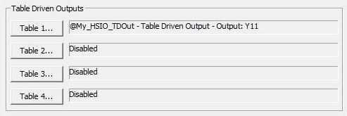
Table 1... / Table 2... / Table 3... / Table 4...: a BX-HSIO module can have up to four Table Driven Outputs. Clicking one of the buttons will open a dialog where that Table Drive Output is given a name and the physical output used by that table is selected. A full discussion of how to configure and use these outputs can be found at BRX Table Driven Outputs.
After the High-Speed I/O discrete output has been selected for use as a Table Driven Output, it is controlled using a Preset Table (a table of preset values and an associated action), or a Programmable Limit Switch which uses a table of value which define alternating ON and OFF edge positions, for example, the lobes on a cam.
TDOPLS - Load Programmable Limit Switch Table for Table Driven Output
TDOPRESET - Load Preset Table for Table Driven Output
Interrupt Functions
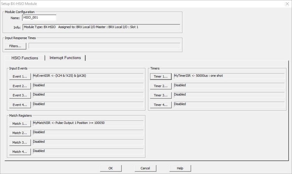
Event Triggers
BRX MPUs can use the inputs on BRX HSIO modules (BX-HSIO1, BX-HSIO2) to trigger the execution of an Interrupt Service Routine. The triggering Event is constructed from the input's current state of the selected input (a High / Low Level), and transitions between states of the selected input (a Rising / Falling / Either Edge).
See the BRX Interrupt Triggers help topic for a complete discussion on Setting Up Input Events.
Register Match Triggers
When one of the BRX CPU's on-board a High-Speed I/O inputs or one of the inputs on a BRX HSIO module (BX-HSIO1, BX-HSIO2) is configured for high speed counting, a register match operation can be used to generate a Match Register Event to trigger the execution of an Interrupt Service Routine. Once enabled, the ISR will be run each time the comparison operation transitions from "not a match" to "is a match".
See the BRX Interrupt Triggers help topic for a complete discussion on Setting Up Register Match Events.
Timer Triggers
BRX HSIO modules (BX-HSIO1, BX-HSIO2) use a hardware timer to run an Interrupt Service Routine in situations where you need an action to occur at regular intervals and not be affected by variations in the PLC scan time. For example, situations that require actions occur at precise repeating intervals, or actions that occur after a precise amount of delay time.
See the BRX Interrupt Triggers help topic for a complete discussion on Setting Up Timer Events.