Topic: DMD0397

AXJOG - Axis Jog Mode
Note: this instruction can only be used with a BRX CPU !
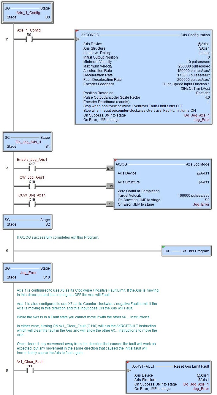
The Axis Jog Mode (AXJOG) instruction sets an Axis into a mode where it's position can be manually adjusted by moving the Axis in the forward and reverse direction. Jogging is a velocity move that uses the Acceleration and Deceleration parameters specified in the Axis Configuration to ramp up to and ramp down from the Maximum Velocity specified in the AXJOG instruction or the Maximum Velocity specified in the Axis Configuration - whichever is lower.
This instruction can optionally override the Maximum Acceleration and Deceleration for the duration of the instruction, and / or optionally set the Axis' position to 0 when the instruction ends. See the Axis Configuration (AXCONFIG) instruction for details on these other parameters.
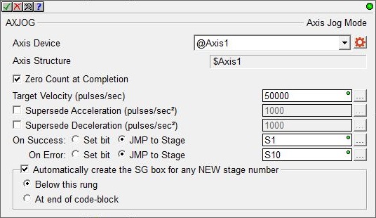
Axis Device selects which Axis this instruction will use - remember that Axis 0 is a virtual Axis meaning it will not generate pulses to physical outputs on the PLC.
Axis Structure displays the name of structure associated with this Axis. This structure was automatically created when the Axis itself was created.
Click the gear symbol at the right end of the Axis Device to open the BRX Axis / Pulse Outputs configuration dialog where the Axis' Pulse Output Mode is set and its High-Speed I/O outputs are selected.
If the Zero Count at Completion option is enabled the Current Position of the Axis will be set to 0 when the Enable / Reset input transitions from ON to OFF. If not enabled the Axis will retain the contents of the Current Position after the Jog is complete.
Target Velocity specifies the velocity this Jog instruction will ramp to during a Forward or Reverse move. If this value is higher than the Maximum Velocity specified in the Axis' Configuration, the Axis' Maximum Velocity value will be used instead of the specified value. Forward and Reverse moves will use the Axis Configuration's Acceleration and Deceleration values when ramping up to and ramping down from the maximum allowed velocity. This can be any positive constant value or any numeric memory location.
Note: do not write directly to the .TargetVelocity member of Axis' associated structure to specify the velocity of the jog operation; only use the Target Velocity parameter in this instruction to specify the jog velocity. Writing directly to the Axis' .TargetVelocity value can cause the Axis to move unexpectedly.
Enable the Supercede Acceleration option to have the Axis use the specified acceleration rate when performing this JOG operation instead of the current Axis configuration values. This can be any positive constant greater than 0 or any numeric location with a value in that range.
Enable the Supercede Deceleration option to have the Axis use the specified deceleration rate when performing this JOG operation instead of the current Axis configuration values. This can be any positive constant greater than 0 or any numeric location with a value in that range.
Note: These two selections do NOT change the Acceleration and / or Deceleration values in the Axis configuration, these parameters are only used during this particular JOG operation. You can use the Set Axis Properties (AXSETPROP) instruction to make global runtime changes to an Axis' configuration.
This instruction puts the specified Axis into an operational mode - as opposed to performing a single operation. Because this is a mode change operation, ON Success is defined as getting the Axis into this mode and back out of this mode with no errors or faults.
When the input logic turns ON, the On Error indication will turn ON if there is a problem getting the Axis into the this operational mode. It will remain OFF if the mode change is successful.
Once the Axis is in this mode, the On Success indication will turn ON after the input logic turns OFF and the Axis' decelerates to 0 (the Current Velocity reaches 0). At this point the Axis' Mode will be "Idle". Once the input logic turns OFF and the deceleration phase begins, if the input logic turns back ON while the Axis is still decelerating, the Axis will NOT start moving again. You must wait until the On Success indication turns ON - the Axis must be "Idle" - before attempting to run any other Axis instruction.
The On Success and On Error parameters specify what action to perform when this instruction completes. You do not have to use the same type of selection for both On Success and On Error.
If the Set Bit selection is used for either On Success or On Error, the specified BIT location will be SET OFF when the instruction is first enabled and will remain OFF until the instruction completes. Once complete, the appropriate Success or Error bit location will be set ON. The specified Bit location is enabled with a SET (Latch) operation not an (OUT) operation meaning that it will remain ON even if this instruction's input logic goes OFF.
If the JMP to Stage selection is used for either On Success or On Error the target Stage must be in the same Program code-block as this instruction, you cannot specify a target Stage that exists in a different Program code-block. When the operation finishes, the target Stage will be enabled the same way as a standalone Jump to Stage (JMP) instruction would do it. The JMP to Stage option will only be selectable if this instruction is placed in a Program code-block.
On Success selects which of the following actions to perform if the operation is successful:
- Enable Set Bit then specify any writable bit location.
- Enable JMP to Stage then specify any Stage number from S0 to S127
in the current Program code-block.
On Error selects which of the following actions to perform if the operation is unsuccessful:
- Enable SET Bit then specify writable bit location.
- Enable JMP to Stage then specify any Stage number from S0 to S127
in the current Program code-block.
If either the On Success or On Error selections are set to JMP to Stage, Automatically create the SG box for any NEW stage number will be enabled which will automatically create any target stage that does not already exist.
- Below this rung will create the new target stage on a new rung following this instruction.
- At end of code-block will create the new target stage as the last rung of this Program.
Inputs Legs:

The Axis Jog (AXJOG) has the following three ladder logic inputs:
The first input leg is the (Enable / Reset) input. When this input is ON the instruction will run, and when OFF the instruction will stop running and reset its status data. Once enabled, the Forward and Reverse inputs will function.
The second input leg is the Forward input . When this input is ON the Axis will ramp up in the clockwise direction from the current Velocity to the Maximum Velocity allowed and will continue to move in this direction as long as the input is ON. When this input is OFF the Axis will ramp down to 0 in the clockwise direction.
The third in put is the Reverse input. When this input is ON the Axis will ramp up in the counter-clockwise direction from the current Velocity to the Maximum Velocity allowed and will continue to move in this direction as long as the input is ON. When this input is OFF the Axis will ramp down to 0 in the counter-clockwise direction.
Note: An Axis cannot change direction until the Axis has stopped moving. This means that if the Forward input is ON causing the Axis to move clockwise and the Reverse input comes ON, the Axis will ramp down to 0 and remain stopped until either the Forward or Reverse input goes OFF.
Note: While an Axis is jogging, if <Axis>.Suspend is turned ON the Axis will ramp down to 0 using the Axis' Deceleration value, when <Axis>.Suspend is turned OFF the Axis will ramp up to the Maximum Velocity allowed using the Axis' Acceleration value.
Note: While an Axis is Jogging, if <Axis>.EnableOutput is turned OFF the Axis will immediately stop moving - it will NOT ramp down. The Axis will continue to run and update the Current Position and Current Velocity in the associated structure but the Axis will NOT drive the physical High-Speed I/O outputs. If this bit is turned back ON the Axis will attempt to start moving again at the Current Velocity. It will NOT ramp up to the Current Velocity value so the motor may stall if the motor cannot restart at that velocity value.
Note: While an Axis is jogging, if <Axis>.MasterEnable is turned OFF the Axis will ramp down using the Fault Deceleration Rate from the Axis. This should only be done when the Axis needs to be shutdown immediately and stop any movement of the Axis. The proper way to recover from this is to re-run the Axis Configuration (AXCONFIG) instruction that configures this Axis.
Note: While an Axis is Jogging, if either of the Fault Limits is reached the Axis will ramp down using the Fault Deceleration Rate from the Axis. The Axis will remain in a Fault state until a Reset Axis Limit Fault (AXRSTFAULT) instruction is executed to clear the fault data in the Axis.
Status Display
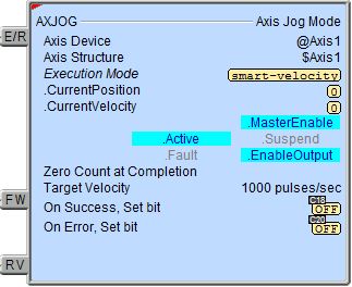
The red triangle in the upper left corner of the status display indicates this is a Fully Asynchronous instruction.
Execution Mode shows the current mode of the Axis (see a list of the possible execution mode values).
Execution Mode / CurrentPosition / CurrentVelocity are the current values of these numeric fields from Axis' associated structure.
MasterEnable / Active / Suspend / Fault / EnableOutput are the current state of these Bit values from that Axis' associated structure.
A detailed description of the Numeric and Bit fields is available in AXCONFIG - Axis Configuration.
See Also
AXSETPROP - Axis Set Properties
AXRSTFAULT - Reset Axis Limit Fault
AXSCRIPT - Run a Sequence of Axis Commands
AXHOME - Axis Perform Home Search
AXPOSTRAP - Axis Move to Position Using Trapezoid
AXPOSSCRV - Axis Move to Position Using S-Curve
AXVEL - Axis Set Velocity Mode
AXGEAR - Axis Electronic Gearing
AXFOLLOW - Axis Position Following with Offset
AXCAM - Axis Electronic Camming
Related Topics
Example