Topic: DMD0445

Module Configuration for BX-SERIO, BX-SERIO-2, and BX-SERIO-4 Serial Communication Modules
When a Do-more CPU powers up and detects a new BX-SERIO, BX-SERIO-2, or BX-SERIO-4 module it will automatically create a new module configuration. Clicking the Edit Config button in the Module Configuration utility will open the following dialog where the default configuration can be changed. The configuration options that will be available will depend on which of the SERIO module variants is being configured.
The Module Configuration Name will become a Do-more device; be careful to choose a meaningful and unique name. Module
names must follow Nickname Rules![]() Nicknames can be 1 to 16 characters in length and consist of any combination of alphanumeric characters and underscores ('_', 'a-z', 'A-Z', 0-9), no spaces or punctuation marks are allowed, and must begin with a letter or an underscore..
Nicknames can be 1 to 16 characters in length and consist of any combination of alphanumeric characters and underscores ('_', 'a-z', 'A-Z', 0-9), no spaces or punctuation marks are allowed, and must begin with a letter or an underscore..
Each Port A / B / C / D Name will become a Do-more device; be careful to choose a meaningful and unique name.
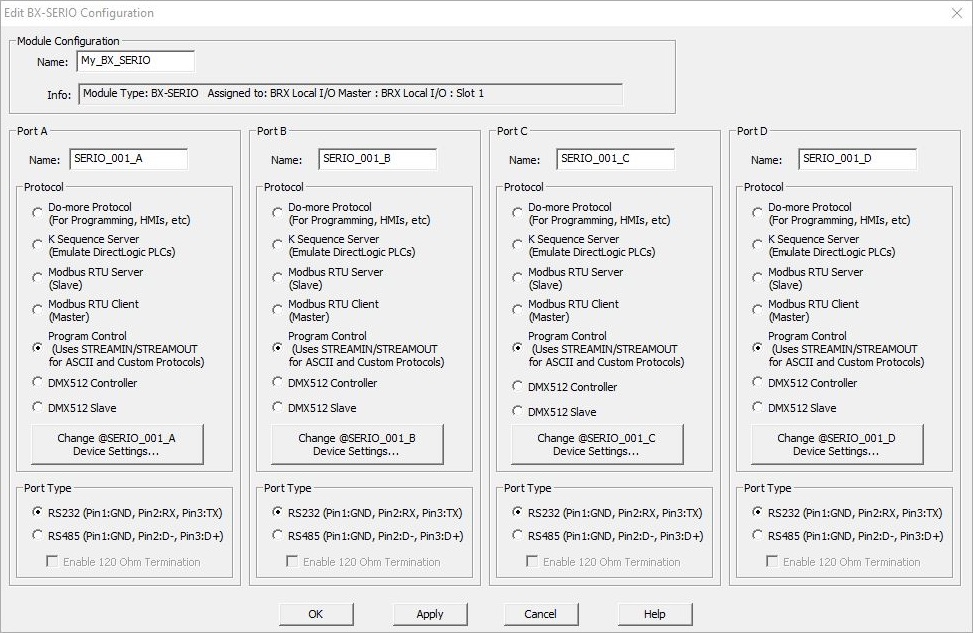
The Protocol group selects the communication protocol each of the serial ports on all of the BX-SERIO module variants. Each protocol selection has an associated device that is specific to that mode; changing the mode will cause the underlying device to be deleted and / or created as needed. Refer to the individual protocol sections for details about the protocol selection options.
Changing the Protocol selection can have a significant impact on the System Configuration; to minimize unintended conflicts, any changes that are made will not be committed until the 'OK' or Apply' button is clicked. After selecting the Protocol for a port, click the Apply button to commit that selection.
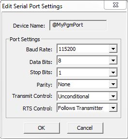
Once the Protocol is selected, click the Change <Port Name> Device Settings... button for that port to configure the Baud Rate, Parity, Station Address, etc., for that individual port. Each of the Protocol selections will have the same serial port hardware configuration with the following parameters:
Baud Rate : 115200, 57600, 38400, 19200, 9600, 4800, 2400, 1200, 300
Data Bits : 7, 8
Parity : None, Odd, Even
Unconditional means the data will be transmitted as soon as it reaches the output buffer.
Wait for CTS means the data will be transmitted when the CTS line is asserted.
Delayed 5ms, Delayed 50ms, Delayed 250ms, Delayed 500ms means that after data reaches the output buffer, the RTS line will be asserted, and the transmitting of the data will be delayed by the selected number of milliseconds.
The Port Type group selects the underlying hardware configuration for the serial ports. Depending on which BRX SERIO module variant that is being configured, the 4 serial ports can be independently configured as follows:
The BX-SERIO allows all of the ports to operate as either an RS-232 port (the default) or an RS-485 port.
Select the RS-232 (Pin 1: GND, Pin 2: RX, Pin 3: TX) option to have the port operate in point-to-point RS-232 mode.
Select the RS-485 (Pin 1: GND, Pin 2: D+, Pin 3: D-) option to have the port operate in either multi-drop or point-to-point RS-485 mode. If RS-485 mode is selected, enable the Enable 120 Ohm Termination to have the CPU include the on-board 120 Ohm termination resistor between D+ and D- connections. The termination resistor is typically enabled on the RS-485 device at each end of the cable; RS-485 devices in the middle of the cable leave the termination resistor disabled.
The BX-SERIO-2 is fixed with all of the ports configured to operate in point-to-point RS-232 mode with hardware flow control optionally enabled.
The BX-SERIO-4 is fixed with all of the ports configured to operate in either point-to-point or multi-drop RS-422 mode.
Protocol Selection details:
Select Do-more Programming to have the serial port operate as a programming port for the Do-more Designer programming software, or when using this port with an external HMI that is using the Do-more Serial"protocol; for example, the Automationdirect C-More panel. Devices that connect with the Do-more protocol will have access to all of the memory blocks and data structures in the Do-more CPU. Other than the generic port setting described above, there are no additional parameters to configure with this selection.
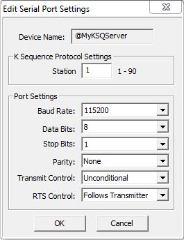
Select K-Sequence Server to connect a third-party device that communicates via K-Sequence protocol. K-Sequence is a proprietary protocol used by Automationdirect (Koyo) hardware. In addition to the generic port settings described above, the Station specifies the ID of the K-Sequence Server device, this can be any constant from 1 to 90.
Devices that connect with the K-Sequence protocol will only have access to the following blocks of memory (these blocks are numbered in octal):
DLX (discrete inputs), default range: DLX0 - DLX777
DLY (discrete outputs), default range : DLY0 - DLY777
DLC (control relays), default range: DLC0 - DLC777
DLV (v-memory registers), default range: DLV0 - DLV3777
Note: The size of the memory blocks available to the K-Sequence driver can be changed in the Memory Configuration.
Select Modbus RTU Server (Slave) to allow a third-party device that communicates via Modbus/RTU protocol to connect to the serial port. In addition to the generic port settings described above, the Unit ID specifies the unique ID of the Modbus/RTU Server device, this can be any constant from 0 to 255.
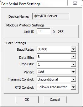
Devices that connect with the Modbus/RTU protocol will only have access to the following blocks of memory (these blocks are numbered in decimal):
MI (modbus inputs), default range: MI1 - MI1023
MC (modbus coils), default range: MC1 - MC1023
MIR (modbus input registers, default range: MIR1 - MIR2047
MHI (modbus holding registers), default range: MHR1 - MHR2047
Note: The first address in each of these memory blocks is offset 0, but the Modbus protocol does not support access to the first address of these memory blocks. The size of the memory blocks available to the Modbus/RTU server can be changed in the Memory Configuration.
The Modbus/RTU Server (Slave) supports the following function codes:
22: Mask Write Register
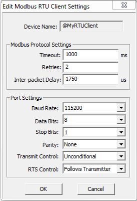
Select Modbus RTU Client (Master)to allow the serial port to be used by the Modbus Network Read (MRX) and the Modbus Network Write (MWX) instructions. In addition to the generic port settings described above there are three additional parameters to configure:
Timeout is how many milliseconds should the instruction wait for the remote Modbus RTU Server to respond, this can be any constant from 0 to 32767.
Retries are how many times should the instruction retry the communication with the remote Modbus RTU Server, this can be any constant from 0 to 255.
Inter-packet Delay is the amount of time (in microseconds) that will be placed between the Modbus RTU packets as they
are sent. This can be any constant between 0 and 65535. The inter-packet delay creates the required "dead time" on the wire that Modbus uses to frame a packet.
The Modbus specification requires this value to be a minimum of 3.5 characters times (based on baud rate). If the value entered is
smaller than the required time, the Modbus RTU Client will use the minimum required time instead of the value that
is entered. If the value entered is larger than the required time, the value entered will be used.
Use this formula to calculate the inter-packet delay (in microseconds) based on baud rate:
( 3.5 * (number of bits in a character / baud rate) ) * 1,000,000
For example: using a 10-bit character (1 start bit, 8 data bits, no parity bit, and 1 stop bit) at 19200 baud:
( 3.5 ( 10 / 19200 ) ) * 1,000,000 = 1823 microseconds
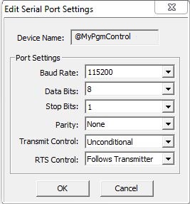
Select Program Control to allow the serial port to be used by the Stream In Data from Device (STREAMIN) and Stream Out Data to Device (STREAMOUT) instructions for sending and receiving ASCII data, or implementing custom protocols. Other than the generic port setting described above, there are no additional parameters to configure with this selection.
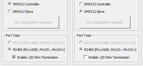
On the BX-SERIO module only, the final two selections put the serial port into DMX512 mode - either as a Controller or a Slave - which allows the SERIO module to connect the Do-more CPU to a DMX512 network. When either DMX512 option is selected, the Port Type is fixed at RS-485 and the port settings are fixed at 250k baud, one start bit, eight data bits, two stop bits and no parity.
Select DMX512 Controller to connect as a client (master) to a DMX512 network. Select DMX512 Slave to connect as a slave (server) on a DMX512 network. See the Help Topic on Using the BX-SERIO with DMX512 Protocol for a full explanation of how to use the BX-SERIO module to participate on a DMX512 network.