Topic: DMD0403

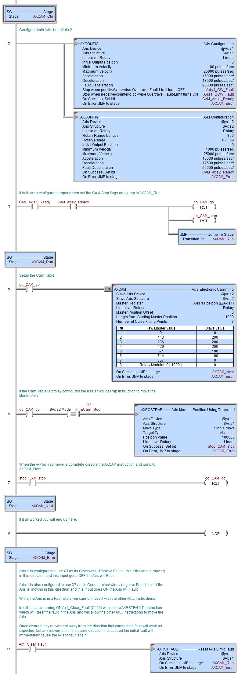
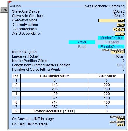
AXCAM - Axis Electronic Camming
Note: this instruction can only be used with a BRX CPU !
The Axis Electronic Camming (AXCAM) instruction is used to establish a Master / Slave connection for an Axis so that its movement is synchronized to another Axis or a High-Speed Counter / Timer. The Slave Axis' position is derived from the Master's position so that any time the Master Axis moves to a new position the Slave Axis will also move to the corresponding position as described in the Cam Table.
Cam Tables are entered as a series of up to 64 segments. All of the segments are the same size; they are equal divisions of the total span of the Master Axis movement. The AXCAM instruction uses Cubic Interpolation to generate a cubic trajectory between each pair of entries in the table. When executing these segments, the CPU will fit a smooth curve to the data which will pass through every point in the table.
Slave Axis Device specifies which Axis to use as the Slave Axis. If the Master Register is one of the on-board Axes, the Slave Axis can only be one of the other on-board Axes. If the Master Register is on an HSIO1, HSIO2, or HSIO4 module, it can only be one the other Axes on the same HSIO module.
Slave Axis Structure is the structure associated with this Axis. This structure is automatically created when the Axis itself is created.
Click the gear symbol to the right of the Slave Axis Device field to open the BRX Axis / Pulse Outputs dialog in the System Configuration where the Axis' Pulse Output Mode is set and its High-Speed I/O outputs are selected.
Note: to make it possible for the Master and Slave Axes to get synchronized - and remain synchronized - the performance of the Slave axis must be significantly higher than the Master axis. Setting values for the maximum frequency, maximum acceleration, and maximum deceleration of the Slave axis to at least twice those of the Master axis is a good starting point.
Master Register selects the Axis or High-Speed Counter / Timer that provides the position source value. This can be any of the Axes or High-Speed Counter / Timers.
Non-Axis Master Filter Time is only enabled if the Master Register is a High-Speed Counter / Timer. This value is a Filter Time Constant which specifies the rate at which the Master's velocity is calculated. This can be any constant value or any numeric location.
Click the gear symbol at the right end of the Master Register field to open the BRX Axis / Pulse Outputs configuration dialog where the Axis' Pulse Output Mode is set and its High-Speed I/O outputs are selected.
Linear vs. Rotary selects how the Slave position is determined based on the type of movement that the output pulses will generate.
Linear actuators move forward or backwards on a fixed linear path. The movement of linear actuators are defined in linear units such as inches or millimeters. Since linear actuators only move in two directions on a fixed path, linear actuators are defined as finite meaning they have a set distance that they can travel in either direction before they must stop.
If the Master Register value goes outside the bounds of the table the AXCAM instruction DOES NOT clamp the slave value. If the Master Register value goes below 0 the Slave value is extrapolated using the first two points in the table. If the Master Register value goes above the final location in the table the Slave value is extrapolated using the last two points in the table.
Rotary actuators produce rotary motion, meaning that the actuator revolves on a circular path. Movement from this type of actuator is defined in rotary units, typically degrees. A rotary table doesn’t have a fixed distance it can travel; it can keep spinning in the same direction for as long as necessary. The count for a rotary input is kept within a defined range. When the input goes beyond one end of this range, the count wraps to the other end of the range.
If the Master Register value goes below 0 it wraps to the final value in the table. If the Master Register value goes above the final location in the table it wraps to the first location in the table. This guarantees the Master Register value will never generate a value with no corresponding Slave value in the table.
Master Position Offset is a pulse count value that is added to the Master Axis position before the associated Slave position value is calculated which allows the table to start at a non-zero offset. This can be any constant value or any numeric location. If this value is a numeric location, the value is read from that location only when the instruction is first enabled. If this value is non-zero or a numeric location the Raw Master Value column will display the Raw Master Value + Master Offset Position value.
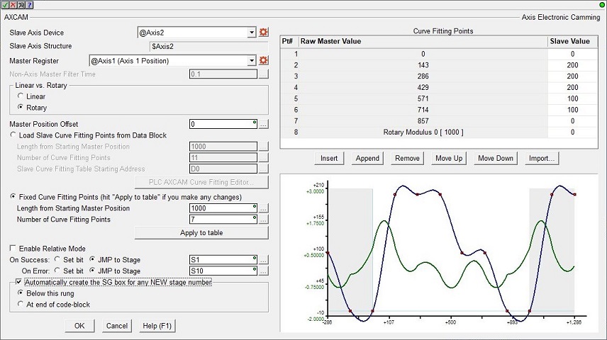
Load Slave Curve Fitting Points from Data Block is the data for the Cam Table segments is located in PLC memory.
Length from Starting Master Position is the total number of pulse counts the Master will move. This can be any positive integer greater than 1 or any numeric location.
Number of Curve Fitting Points is the number of equal-length segments the Length from Master Position will be divided into. There must be at least 3 curve fitting points in the table with a maximum of 64. This can be any positive integer between 3 and 64, or any numeric location containing a value in that range. If the value in a specified numeric location is greater than 64, only the first 64 values will be used.
Slave Curve Fitting Table Starting Address is the beginning address in PLC memory where the curve data is stored. This must be a Signed DWord numeric data block - structure members not allowed..
PLC AXCAM Curve Fitting Editor... - (only available when online with the PLC) click this to open the Curve Fitting Editor which allows you to edit the data values in the specified Data Block. The data configuration options on this dialog are the same as the main dialog.
Initial values in the table editor for AXCAM Slave Table Start Address, Linear vs Rotary, Master Position Offset, Length from Starting Master Position, and Number of Points to be Readcome from the main instruction editor. If these values are changed while editing the table data with this dialog those values will be updated on the main instruction editor when this dialog is closed.
If the Number of Curve Fitting Points, Master Position Offset, and Length from Starting Master Position are variables the value in those locations are read and that many of rows of data are read from the PLC to prefill the table. The Also Write Number of Curve Fitting Points, Also Write Master Position Offset, and Also Write Length from Starting Master Position selections will also be enabled and those variable locations will be prefilled here so that when the table data is written back to the PLC those locations will be updated as well.
The Curve Fitting Points table displays the selected range of master position divide into the specified number of equal segments. Enter the slave values for each of the segment. A slave value can be any positive or negative integer value.
Insert Row will add an empty row above the currently highlighted row in the table. Append Row will add an empty row at the end of the table. Delete Row will remove the highlighted row from the table.
Move Up / Move Down will move the selected slave value one position toward the top or the bottom of the table respectively.
Clear Table removes all of the Slave data from the Table but leave the rows and Master values intact and set all of the Slave values to 0.
Import... will import the contents of the Curve Fitting Points table from a CSV file. The format of the import file is one positive or negative integer per line with a maximum of 64 lines.
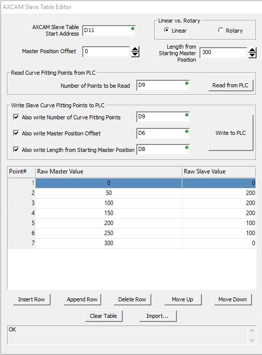
A graph of the current set of Curve Fitting Points is displayed in the section to the right of the editor.
Plot selects which graphs are displayed on the graph.
Both Slave Curve and the Slave / Master Slope Curve or Only Slave Curve or Only Slave / Master Slope Curve.
Highlight (Master , Slave) Points from Table (RED dots) shows the curve fitting points on the graph as RED dots.
Draw (0,0) Origin Axes (LIGHT BLUE Lines) shows the origin lines on the graph in Light Blue.
Gray Out Rotary Outer Regions: in Rotary Mode this selection lets you turn off the two regions with gray backgrounds that shows where the repeating pattern of the curve begins and ends.
Show Crosshairs at Mouse Cursor: when the mouse cursor is over the graph a set of crosshairs is automatically generated. This option turns off the display of the crosshairs.
Zoom: Clicking on the graph will zoom into that segment.
Use the Zoom Pan Left / Zoom Pan Right to move the zoomed area one segment to the left or right respectively. Zoom Out will return the graph to the normal zoom level. Clicking on the graph while zoomed will open the AXCAM Data Point dialog that shows the current Master and Slave point and the slope of the Slave curve at the crosshair.
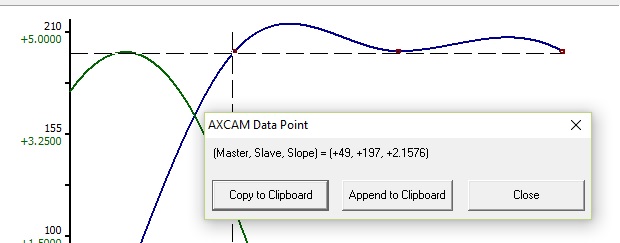
Copy to Clipboard will copy the Master, Slave and Slope values to the Windows clipboard.
Append to Clipboard will add the Master, Slave and Slope values to the existing contents of the Windows clipboard.
Fixed Curve Fitting Points is the data for the Cam Table is in the instruction.
Length from Starting Master Position is the total number of pulse counts the Master will move. This can be any positive integer greater than 1.
Number of Curve Fitting Points is the number of equal-length segments the Length from Master Position will be divided into. There must be at least 3 curve fitting points in the table with a maximum of 64. This can be any positive integer between 3 and 64.
Apply to Table: if either of the above are changed click this button to apply the changes to the Curve Fitting Points table.
The Curve Fitting Points table displays the selected range of master position divide into the specified number of equal segments. Enter the slave values for each of the segment. A slave value can be any positive or negative integer value.
Insert will add an empty row above the currently highlighted row in the table.
Append will add an empty row at the end of the table.
Remove will remove the currently highlighted row from the table.
Move Up / Move Down will move the selected slave value one position toward the top or the bottom of the table respectively.
Import... will import the contents of the Curve Fitting Points table from a CSV file. The format of the import file is one positive or negative integer per line with a maximum of 64 lines.
A graph of the current Curve Fitting Points is displayed in the area below the editor. This graph will plot the Slave Curve in Blue and the Master / Slave Slope Curve in green. The curve fitting data points will appear as red dots on the Slave (blue) Curve.
In Rotary Mode the graph will include also a region before and after the curves that shows where the repeating pattern of the curve begins and ends.
Clicking on the graph will Zoom into curve where the mouse cursor was located when the click occurred. Clicking on the graph while zoomed will open the following dialog:
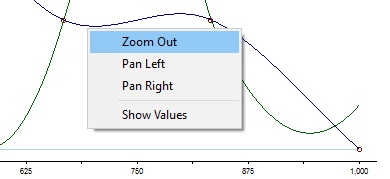
Select Zoom Out to restore the zoom level, or select Pan Left / Pan Right to move the zoomed area one segment to the left or right respectively.
Select Show Values to open the AXCAM Data Point dialog where you can select Copy to Clipboard which will copy the Master, Slave and Slope values to the Windows clipboard, or Append to Clipboard which will add the Master, Slave and Slope values to the existing contents of the Windows clipboard.
Enable Relative Mode: if enabled , when the instruction is enabled, the Slave Axis' current position is stored internally and that position then becomes the new 0 for the Slave Axis. As the Master Axis moves the Slave position values are now relative to this stored position.
This instruction puts the specified Axis into an operational mode - as opposed to performing a single operation. Because this is a mode change operation, ON Success is defined as getting the Axis into this mode and back out of this mode with no errors or faults.
When the input logic turns ON, the On Error indication will turn ON if there is a problem getting the Axis into the this operational mode. It will remain OFF if the mode change is successful.
Once the Axis is in this mode, the On Success indication will turn ON after the input logic turns OFF and the Axis' decelerates to 0 (the Current Velocity reaches 0). At this point the Axis' Mode will be "Idle". Once the input logic turns OFF and the deceleration phase begins, if the input logic turns back ON while the Axis is still decelerating, the Axis will NOT start moving again. You must wait until the On Success indication turns ON - the Axis must be "Idle" - before attempting to run any other Axis instruction.
The On Success and On Error parameters specify what action to perform when this instruction completes. You do not have to use the same type of selection for both On Success and On Error.
If the Set Bit selection is used for either On Success or On Error, the specified BIT location will be SET OFF when the instruction is first enabled and will remain OFF until the instruction completes. Once complete, the appropriate Success or Error bit location will be set ON. The specified Bit location is enabled with a SET (Latch) operation not an (OUT) operation meaning that it will remain ON even if this instruction's input logic goes OFF.
If the JMP to Stage selection is used for either On Success or On Error the target Stage must be in the same Program code-block as this instruction, you cannot specify a target Stage that exists in a different Program code-block. When the operation finishes, the target Stage will be enabled the same way as a standalone Jump to Stage (JMP) instruction would do it. The JMP to Stage option will only be selectable if this instruction is placed in a Program code-block.
On Success selects which of the following actions to perform if the operation is successful:
- Enable Set Bit then specify any writable bit location.
- Enable JMP to Stage then specify any Stage number from S0 to S127
in the current Program code-block.
On Error selects which of the following actions to perform if the operation is unsuccessful:
- Enable SET Bit then specify writable bit location.
- Enable JMP to Stage then specify any Stage number from S0 to S127
in the current Program code-block.
If either the On Success or On Error selections are set to JMP to Stage, Automatically create the SG box for any NEW stage number will be enabled which will automatically create any target stage that does not already exist.
- Below this rung will create the new target stage on a new rung following this instruction.
- At end of code-block will create the new target stage as the last rung of this Program.
Status Display
The red triangle in the upper left corner of the status display indicates this is a Fully Asynchronous instruction.
Execution Mode shows the current mode of the Axis (see a list of the possible execution mode values).
CurrentPosition / CurrentVelocity / MstSlvCoordError are the current values of these numeric fields from Axis' associated structure.
MasterEnable / Active / Suspend / Fault / EnableOutput are the current state of these Bit values from that Axis' associated structure.
See Also
AXSETPROP - Axis Set Properties
AXRSTFAULT - Reset Axis Limit Fault
AXSCRIPT - Run a Sequence of Axis Commands
AXHOME - Axis Perform Home Search
AXPOSTRAP - Axis Move to Position Using Trapezoid
AXPOSSCRV - Axis Move to Position Using S-Curve
AXVEL - Axis Set Velocity Mode
AXGEAR - Axis Electronic Gearing
AXFOLLOW - Axis Position Following with Offset
AXCAM - Axis Electronic Camming
Related Topics
Example