Topic: DMD0399

AXSCRIPT - Run a Sequence of Axis Commands
Note: this instruction can only be used with a BRX CPU !
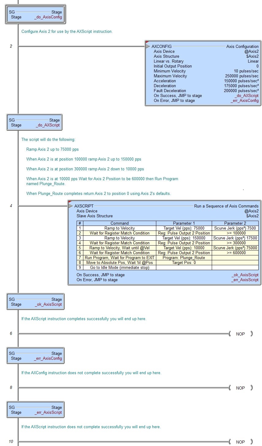
The Run a Sequence of Axis Commands (AXSCRIPT) instruction is used to process a series of commands that can control an Axis, change PLC memory items, and interact with the ladder logic. This series of commands allow for Axis movements that cannot be done with the existing Axis instructions. You should only be using the AXSCRIPT instruction if the other Axis instructions don't give you the control over that Axis that you need. Although some of the Axis-control commands have similar sounding names to the existing Axis instructions, but they do not work exactly the same.
Unlike the other Axis instructions which will leave the Axis in Idle mode when the instruction ends, the AXSCRIPT will leave the Axis in the last state that it was put into by the commands in the instruction when it ends. This can be used to your advantage by allowing you to use the "chain" AXSCRIPT commands together. And because the other Axis instructions can start from any velocity / position, you can use an AXSCRIPT to start a move then finish the move with any of the other Axis instructions (which will end with the Axis in Idle mode.
If the parameters for any of the commands use a PLC memory location instead of a constant value, the instruction will use the value in those parameter locations when the step gets loaded.
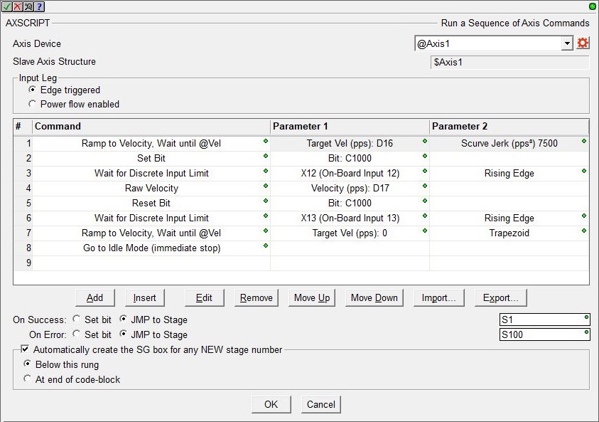
Axis Device selects which Axis this instruction will use - remember that Axis 0 is a virtual Axis meaning it will not generate pulses to physical outputs on the PLC.
Axis Structure displays the name of structure associated with this Axis. This structure was automatically created when the Axis itself was created.
Click the gear symbol at the right end of the Axis Device to open the BRX Axis / Pulse Outputs configuration dialog where the Axis' Pulse Output Mode is set and its High-Speed I/O outputs are selected.
Input Leg selects how the instruction will run:
- Edge Triggered means the AXSCRIPT will be executed each time the input transitions from OFF to ON. Once an AXSCRIPT is in progress it can only be stopped by manually setting the selected Axis' .MasterEnable structure member to OFF, which will put the Axis into a Fault state.
- Power flow Enabled means the AXSCRIPT will begin when the instruction's input logic transitions from OFF to ON and will run toward completion as long as the input remains ON. This selection has the benefit of being able to interrupt an AXSCRIPT execution by setting the input state to OFF and NOT putting the Axis into a Fault state.
The steps in the instruction's table are listed in the order they will be loaded and executed. Each AXSCRIPT instruction can contain up to 50 steps. A step consists of a command and any parameters that command requires; some require 2 parameters, some only 1, and some have none.
Command is the Axis command or PLC command to execute. Refer to the Available Commands section below for details on the individual commands and their required parameters. Parameter 1 is used by commands that have one parameter, Parameter 2 used by commands that have two parameters.
The buttons below the table provide functions that are used to organize the rows in the table: Add opens the row editor sub-dialog so that a new entry can be added to the end of the table. Insert inserts an empty row before the currently selected row / Edit opens the currently selected row in the row editor sub-dialog / Remove deletes the currently selected row. Move Up / Move Downmoves the currently selected row up one row or down one row respectively.
The Import and Export buttons are used to create steps from a text file, and to save steps to a text file respectively. The Import and Export process and the format of the file is discussed in the section below.
On Success will be ON after the final step of this instruction has completed. This does NOT necessarily mean the Axis has completed the execution of the command in the last step, it simply means the last step itself has completed. For example, if the last step was configured to Ramp to Velocity / "immediately go to next step". When this step is processed the Axis will begin the ramp, and since there are no more steps the instruction will end. At that point the On Success will be set ON before the Axis will complete the ramp operation.
The On Error indication will be ON if the instruction is configured to be Power Flow Enabled and the input logic goes OFF before the instruction completes, or if the Axis faults while this instruction is running .
The On Success and On Error parameters specify what action to perform when this instruction completes. You do not have to use the same type of selection for both On Success and On Error.
If the Set Bit selection is used for either On Success or On Error, the specified BIT location will be SET OFF when the instruction is first enabled and will remain OFF until the instruction completes. Once complete, the appropriate Success or Error bit location will be set ON. The specified Bit location is enabled with a SET (Latch) operation (not an OUT operation) meaning that it will remain ON even if this instruction's input logic goes OFF.
If the JMP to Stage selection is used for either On Success or On Error the target Stage must be in the same Program code-block as this instruction, you cannot specify a target Stage that exists in a different Program code-block. When the operation finishes, the target Stage will be enabled the same way as a standalone Jump to Stage (JMP) instruction would do it. The JMP to Stage option will only be selectable if this instruction is placed in a Program code-block.
On Success selects which of the following actions to perform if the operation is successful:
- Enable Set Bit then specify any writable bit location.
- Enable JMP to Stage then specify
any Stage number from S0 to S127 in the current Program code-block.
On Error selects which of
the following actions to perform if the operation is unsuccessful:
- Enable SET Bit then specify writable bit location.
- Enable JMP
to Stage then specify any Stage number
from S0 to S127 in the current Program code-block.
If either the On Success or On Error selections are set to JMP to Stage, Automatically create the SG box for any NEW stage number will be enabled which will automatically create any target stage that does not already exist.
- Below this rung will create the new target stage on a new rung following this instruction.
- At end of code-block will create the new target stage on the last rung of this Program.
Available Commands:
The commands available for use in the AXSCRIPT instruction are listed in the following functional groups: Velocity, Position, Rotary, Follower, Events, Ladder Operations, Miscellaneous, and Looping..
These commands are entered in the table through the row editor that prompts for the command to execute and any parameters required by that command. And remember, if the parameters for any of the commands use a PLC memory location instead of a constant value, the instruction will use the value in the parameter location when it loads the step that contains the parameter reference.
After selecting the command and entering the parameters, use the buttons at the bottom of the dialog as follows: Save will commit any changes that were made to the command and close the row editor. Save / Next will commit any changes that were made to the command and begin editing the existing command entry in the next row. Save / Insert will commit any changes that were made to the command and create a new command entry below the row you just saved. Cancel will close the row editor without saving any changes that have been made.
Velocity commands approximate the Axis Set Velocity Mode (AXVEL) instruction:
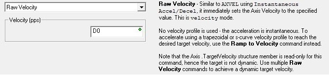
The Raw Velocity command immediately sets the Axis' velocity to the specified Velocity value and immediately moves to the next step in the table.
The Velocity (pps) value can be any constant between -2,000,000 and 2,000,000 or any numeric location containing a value in that range. The sign of the value will indicate the direction of travel: positive numbers will cause the Axis to move clockwise, negative numbers will cause the Axis to move counter-clockwise. Any value that is below the Axis' Configured Minimum Velocity will result in the Axis Minimum Velocity being used. Note: only the BX-HSIO4 module can operate at velocities above 250KHz; attempting to use a velocity above 250KHz for an Axis that is using the on-board High-Speed I/O, or an Axis on a BX-HSIO1 or BX-HSIO2 module will result in a maximum velocity of that Axis still being 250KHz.
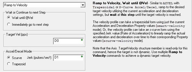
The Ramp to Velocity command sets the Axis' Target Velocity to the specified Velocity value, and the Axis will begin to ramp toward that new Target Value using either an S-Curve (with Jerk) or Trapezoid profile as selected. If Wait Until @Vel is selected, the table will remain at this step until the Axis reaches the Target Velocity. If Immediately go to next step is selected, the table will immediately move to the next step without waiting on the Axis to reach the Target Velocity.
The Target Vel (pps) value can be any constant between -2,000,000 and 2,000,000 or any numeric location containing a value in that range. The sign of the value will indicate the direction of travel: positive numbers will cause the Axis to move clockwise, negative numbers will cause the Axis to move counter-clockwise. Any value that is below the Axis' Configured Minimum Velocity will result in the Axis Minimum Velocity being used. Note: only the BX-HSIO4 module can operate at velocities above 250KHz; attempting to use a velocity above 250KHz for an Axis that is using the on-board High-Speed I/O, or an Axis on a BX-HSIO1 or BX-HSIO2 module will result in a maximum velocity of that Axis still being 250KHz.
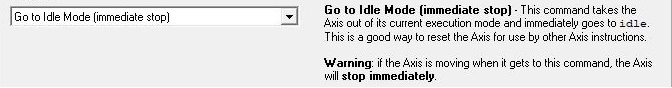
The Go to Idle Mode (immediate stop) command will instruct the Axis to immediately go to IDLE mode which take the Axis out of the current execution mode. If the Axis is moving it will immediately stop; it will NOT ramp to a stop. To avoid potential machine damage you should probably use a Ramp to Velocity of 0 command (to bring the Axis to a controlled stop) before using the Go to Idle command.
Note: unlike the other Axis instructions which will leave the Axis in Idle mode, the AXSCRIPT will leave the Axis in the last state that it was put into by the commands in the instruction. Unless you have a purpose for leaving the Axis in a state where it is potentially moving (not idle) when this instruction finishes, we recommend that you make sure the Axis is not moving when the AXSCRIPT instruction completes by adding a Goto to Idle Mode command as the last step in the table.
Position commands approximate the Axis Move to Position Using Trapezoid (AXPOSTRAP) and Axis Move to Position Using S-Curve (AXPOSSCRV) instructions when making Linear position moves.
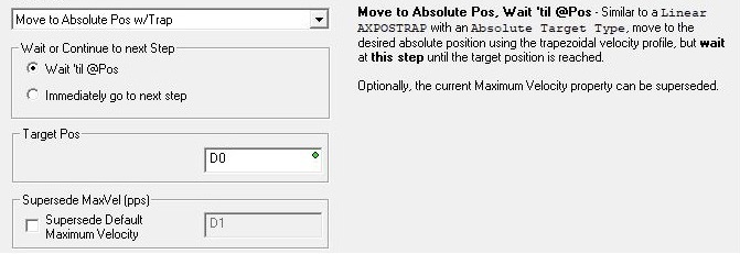
The Move to Absolute Pos w/ Trap command will use a Trapezoid profile to move the Axis to the specified absolute Target Position, optionally using a different Maximum Velocity. If Wait 'til @Pos is selected, the table will remain at this step until the Axis reaches the Target Position. If Immediately go to next step is selected, the table will immediately move to the next step without waiting on the Axis to reach the Target Position.
The Supercede MaxVel (pps) value can be any constant between -2,000,000 and 2,000,000 or any numeric location containing a value in that range. Note: only the BX-HSIO4 module can operate at velocities above 250KHz; attempting to use a velocity above 250KHz for an Axis that is using the on-board High-Speed I/O, or an Axis on a BX-HSIO1 or BX-HSIO2 module will result in a maximum velocity of that Axis still being 250KHz.
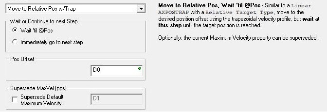
The Move to Relative Pos w/ Trap command will use a Trapezoid profile to move the Axis to the specified relative Position Offset, optionally using a different Maximum Velocity. If Wait 'til @Pos is selected, the table will remain at this step until the Axis reaches the Position Offset. If Immediately go to next step is selected, the table will immediately move to the next step without waiting on the Axis to reach the Position Offset.
The Supercede MaxVel (pps) value can be any constant between -2,000,000 and 2,000,000 or any numeric location containing a value in that range. Note: only the BX-HSIO4 module can operate at velocities above 250KHz; attempting to use a velocity above 250KHz for an Axis that is using the on-board High-Speed I/O, or an Axis on a BX-HSIO1 or BX-HSIO2 module will result in a maximum velocity of that Axis still being 250KHz.
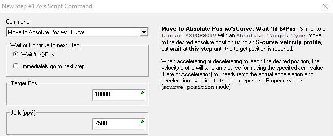
The Move to Absolute Pos w/S-Curve command will use an S-Curve profile to move the Axis to the specified absolute Target Position, optionally using a different Maximum Velocity. If Wait 'til @Pos is selected, the table will remain at this step until the Axis reaches the Target Position. If Immediately go to next step is selected, the table will immediately move to the next step without waiting on the Axis to reach the Target Position.
Note: if an attempt is made to run a Move to Absolute Position w/ S-Curve command at a point when the Axis is accelerating or decelerating (the Axis' .RateOfChange is non-zero), or the target position is in the opposite direction the Axis is currently traveling, or the Axis is moving at a velocity that will not allow it get to the target position without over-shooting, the axis will fault with a 69 (0x45) Fault-SCurve.
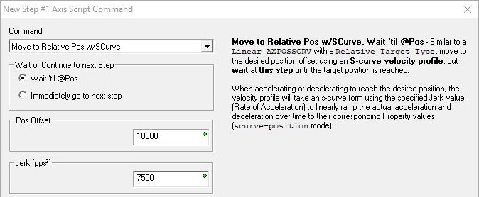
The Move to Relative Pos w/S-Curve command will use an S-Curve profile to move the Axis to the specified relative Position Offset, optionally using a different Maximum Velocity. If Wait 'til @Pos is selected, the table will remain at this step until the Axis reaches the Position Offset. If Immediately go to next step is selected, the table will immediately move to the next step without waiting on the Axis to reach the Position Offset.
Note: if an attempt is made to run a Move to Relative Position w/ S-Curve command at a point when the Axis was accelerating or decelerating (the Axis' .RateOfChange is non-zero), or the target position is in the opposite direction the Axis is currently traveling, or the Axis is moving at a velocity that will not allow it get to the target position without over-shooting, the axis will fault with a 69 (0x45) Fault-SCurve.
Rotary commands approximate the Axis Move to Position Using Trapezoid (AXPOSTRAP) instruction when making Rotary position moves.
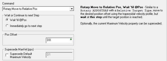
The Rotary Move to Relative Pos command will use a Trapezoid profile to move the Axis to the specified relative Position Offset, optionally using a different Maximum Velocity. If Wait 'til @Pos is selected, the table will remain at this step until the Axis reaches the Position Offset. If Immediately go to next step is selected, the table will immediately move to the next step without waiting on the Axis to reach the Position Offset.
The Supercede MaxVel (pps) value can be any constant between -2,000,000 and 2,000,000 or any numeric location containing a value in that range. Note: only the BX-HSIO4 module can operate at velocities above 250KHz; attempting to use a velocity above 250KHz for an Axis that is using the on-board High-Speed I/O, or an Axis on a BX-HSIO1 or BX-HSIO2 module will result in a maximum velocity of that Axis still being 250KHz.
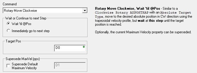
The Rotary Move Clockwise command will use a Trapezoid profile to move the Axis in the clockwise direction to the to the specified Target Position, optionally using a different Maximum Velocity. If Wait 'til @Pos is selected, the table will remain at this step until the Axis reaches the Target Position. If Immediately go to next step is selected, the table will immediately move to the next step without waiting on the Axis to reach the Target Position.
The Supercede MaxVel (pps) value can be any constant between -2,000,000 and 2,000,000 or any numeric location containing a value in that range. Note: only the BX-HSIO4 module can operate at velocities above 250KHz; attempting to use a velocity above 250KHz for an Axis that is using the on-board High-Speed I/O, or an Axis on a BX-HSIO1 or BX-HSIO2 module will result in a maximum velocity of that Axis still being 250KHz.
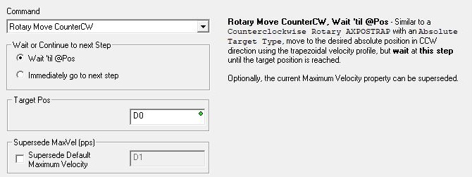
The Rotary Move Counter-Clockwise command will use a Trapezoid profile to move the Axis in the counter-clockwise direction to the to the specified Target Position, optionally using a different Maximum Velocity. If Wait 'til @Pos is selected, the table will remain at this step until the Axis reaches the Target Position. If Immediately go to next step is selected, the table will immediately move to the next step without waiting on the Axis to reach the Target Position.
The Supercede MaxVel (pps) value can be any constant between -2,000,000 and 2,000,000 or any numeric location containing a value in that range. Note: only the BX-HSIO4 module can operate at velocities above 250KHz; attempting to use a velocity above 250KHz for an Axis that is using the on-board High-Speed I/O, or an Axis on a BX-HSIO1 or BX-HSIO2 module will result in a maximum velocity of that Axis still being 250KHz.
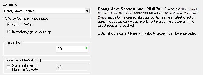
The Rotary Move Shortest command will use a Trapezoid profile to move the Axis in the direction that will reach the specified Target Position in the shortest distance (either clockwise or counter-clockwise), optionally using a different Maximum Velocity. If Wait 'til @Pos is selected, the table will remain at this step until the Axis reaches the Target Position. If Immediately go to next step is selected, the table will immediately move to the next step without waiting on the Axis to reach the Target Position.
The Supercede MaxVel (pps) value can be any constant between -2,000,000 and 2,000,000 or any numeric location containing a value in that range. Note: only the BX-HSIO4 module can operate at velocities above 250KHz; attempting to use a velocity above 250KHz for an Axis that is using the on-board High-Speed I/O, or an Axis on a BX-HSIO1 or BX-HSIO2 module will result in a maximum velocity of that Axis still being 250KHz.
Follower commands approximate the Axis Position Following with Offset (AXFOLLOW) instruction:
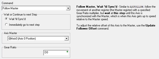
The Follow Master command will establish a Master / Follower connection for the Axis so that the Follower's movements are synchronized to the Master's movement, using the specified Gear Ratio. The Axis Master must be another Axis or a High-Speed Counter / Timer on the same hardware as the Axis Device. Because the Follower Axis will need the ability to get synchronized and stay synchronized with the Master Axis when the Gear Ratio changes, make sure the Follower Axis has been configured with significantly higher maximum velocity, acceleration and deceleration values.
Once the step is reached, the Follower Axis will being moving at the Slave Axis' maximum velocity in an effort to get into "sync" with the Master. If Wait 'til Sync'd is selected, the table will remain at this step until the velocity of the following Axis (including the Gear Ratio) matches the velocity of the master Axis. If Immediately go to next step is selected, the table will immediately move to the next step without waiting for the velocities to match.
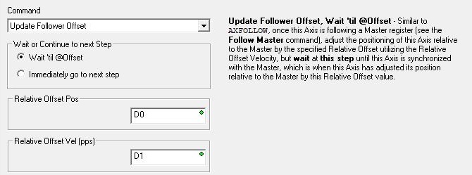
The Update Follower Offset command causes the Follower Axis to attempt to move to the Relative Offset Position using the Relative Offset Velocity. Because the Follower Axis will need the ability to overtake the Master Axis during this operation, make sure the Maximum Velocity and Acceleration parameters of the Master and Follower Axes have been configured with enough capacity to allow this. The Follower Axis can be made more responsive by configuring it with higher Maximum Velocity or a faster Acceleration, or both. A value of 0 for the Relative Offset Velocity will cause the Follower Axis to move at the Axis's maximum Velocity to get to the specified offset position.
The Relative Offset Vel (pps) value can be any constant between -2,000,000 and 2,000,000 or any numeric location containing a value in that range. Note: only the BX-HSIO4 module can operate at velocities above 250KHz; attempting to use a velocity above 250KHz for an Axis that is using the on-board High-Speed I/O, or an Axis on a BX-HSIO1 or BX-HSIO2 module will result in a maximum velocity of that Axis still being 250KHz.
Event commands will wait at the current step on an input event from the Axis.
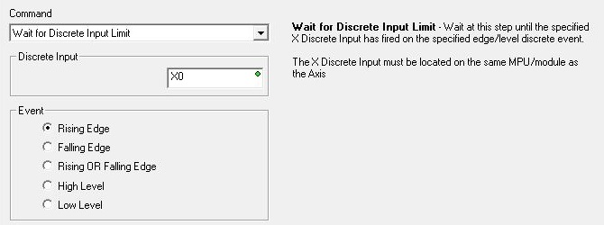
The Wait For Discrete Input Limit command will wait at this step in the table until the selected event occurs on the specified discrete input.
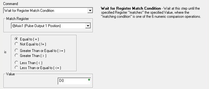
The Wait For Register Match Condition command will wait at this step in the table until the value in the selected Match Register location matches the specified Value using one of the six match conditions.
The Wait Until At Velocity command will wait at this step in the table until the Axis has reached its target velocity (.CurrentVelocity = .TargetVelocity).

The Wait Until At Position command will wait at this step in the table until the Axis has reached its target position (.CurrentPosition = .TargetPosition).

The Wait Until Stopped command will wait at this step in the table until the Axis has stopped moving (.Mode = Idle).

Ladder Operation commands perform actions that interact with elements in the ladder logic program.
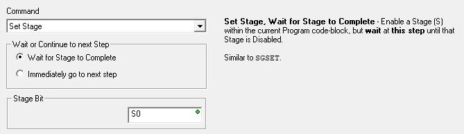
The Set Stage command will enable a Stage in the same Program that contains the AXSCRIPT instruction. This cannot be a Stage in a different Program code-block. If Wait for Stage to Complete is selected, the table will remain at this step until the specified Stage is disabled. If Immediately go to next step is selected, the table will immediately move to the next step without waiting on the Stage to be disabled.
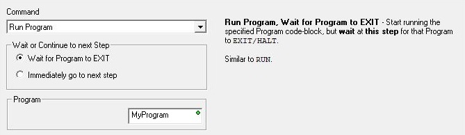
The Run Program command will run the specified Program code-block. If Wait for Program to Exit is selected, the table will remain at this step until the specified Program's .Done bit comes ON. If Immediately go to next step is selected, the table will immediately move to the next step without waiting on the Program to end.
The Start Timer command will start running an internal (millisecond resolution) Timer using the specified Preset value. This is NOT a Timer in the ladder logic; it is a Timer that is internal to the AXSCRIPT instruction. If Wait for Timer to be Done is selected, the table will remain at this step until the specified Timer has timed out. If Immediately go to next step is selected, the table will immediately move to the next step without waiting on the Timer to complete. The Axis' associated structure member .Timer shows the current value of the Timer as it times down to 0.

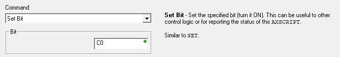
The Set Bit command will turn ON the specified bit location in the same way a Set Coil (SET) instruction does.
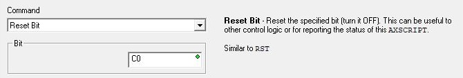
The Reset Bit command will turn OFF the specified bit location in the same way a Reset Coil (RST) instruction does.
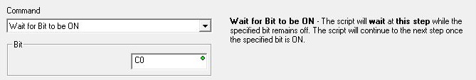
The Wait for Bit to be ON command will wait at this step in the table until the specified Bit location turns ON. This does NOT wait for an OFF to ON transition of the specified Bit; if the Bit is ON when the table gets to this step, the condition will be met and the table will not wait at this step.
The Wait for Bit to be OFF command will wait at this step in the table until the specified Bit location turns OFF. This does NOT wait for an ON to OFF transition of the specified Bit; if the Bit is OFF when the table gets to this step, the condition will be met and the table will not wait at this step.

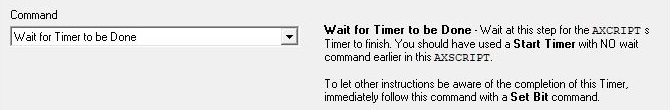
The Wait for Timer to be Done command will wait at this step for the AXSCRIPT's internal (millisecond resolution) Timer to complete. This is NOT a Timer in the ladder logic; it is a Timer that is internal to the AXSCRIPT instruction. The Axis' associated structure member .Timer shows the current value of the Timer as it times down to 0. This is really only useful if the table contains a previously executed "Start Timer / immediately go to next step" command.
Miscellaneous commands
The Set Axis Property command will change the selected Axis parameter without having to re-run an Axis Configuration (AXCONFIG) instruction. Changes made to the Axis by this command will affect all subsequent instructions that reference this Axis, but they will not affect any Axis instructions that are currently running.
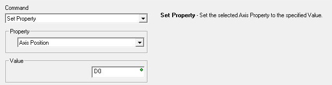
This command lets you set the following properties:
Axis Position is the Current Position of the Axis. This can be any constant value or any numeric location.
Minimum Axis Velocity (pps) is the slowest frequency of output pulses that will be generated when the output is enabled. This can be any positive constant from 10 to 2,000,000, or any numeric location with a value in that range. Note: only the BX-HSIO4 module can operate at velocities above 250KHz; attempting to use a velocity above 250KHz for an Axis that is using the on-board High-Speed I/O, or an Axis on a BX-HSIO1 or BX-HSIO2 module will result in a maximum velocity of that Axis still being 250KHz.
Maximum Axis Velocity (pps) is the fastest frequency of output pulses that will be generated when the output is enabled. This can be any positive constant from 10 to 2,000,000, or any numeric location with a value in that range. Note: only the BX-HSIO4 module can operate at velocities above 250KHz; attempting to use a velocity above 250KHz for an Axis that is using the on-board High-Speed I/O, or an Axis on a BX-HSIO1 or BX-HSIO2 module will result in a maximum velocity of that Axis still being 250KHz.
Axis Acceleration (pps2) is the rate at which the velocity will change when the Axis is ramping up from a slower pulse rate to a higher pulse rate, effectively it is how quickly to move from the current velocity to the maximum velocity. This can be any positive constant greater than 0 or any numeric location with a value in that range.
Axis Deceleration (pps2) is the rate at which the velocity will change when the Axis is ramping down from a faster pulse rate to a slower pulse rate, effectively it is how quickly to move from the current velocity to the minimum velocity. This can be any positive constant greater than 0 or any numeric location with a value in that range.
Encoder/Pulse Scale Factor: if the pulse count and the encoder have different pulse-per-revolution values, enter the scale value required to bring them into alignment.
Encoder/Pulse Deadband : having some deadband value around the encoder current position can prevent the pulse output from generating alternating small pulses trying to get the input value to an exact number. This value is applied both above and below the encoder value, for example, a value of 2 will be a deadband of 2 above and two below for a span of 4 counts.
Rotary Range is the range of count values for one complete rotation.
Non-Axis Master Filter Time (Sec) is only applicable if the Master Register is a High-Speed Counter / Timer. This value is a Filter Time Constant which specifies the rate at which the Master's velocity is calculated.
Fault Deceleration (pps2) : any time a Fault Limit is reached or the Axis' MasterEnable is manually turned OFF, the Axis will decelerate to a velocity of 0 pulses / sec at this specified rate. This can be any positive constant value or any numeric location with a value in that range.
Fault Deceleration Stop Immediately sets the Axis' Fault Deceleration 0. A value of 0 will cause the Axis to immediately stop moving (not decelerate to 0) when a Fault occurs on the Axis.
Looping commands allow the AXSCRIPT to repeat a section of the commands in the table. Loops can not be nested.
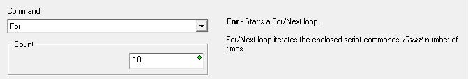
The For command begins a For / Next loop where the commands between the For and the Next commands will be executed a predefined number of times. The Count value can be any constant value greater than 1, or a numeric location contain a value greater than 1. Note: if the numeric location contains a value less than 1, the For loop will still operate as though the value is 1, meaning you will still get one pass through the loop for values less than 1.
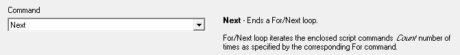
The Next command marks the end of a For / Next Loop.
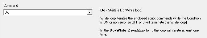
The Do command begins a Do / While Loop where the commands between the Do and the While commands will be repeated as long as the condition in the ending While condition is ON (if Boolean) or contains a non-zero value (if numeric). Because the check for the condition is in the closing While command, there will always be at least one pass through the commands in the Do / While loop.
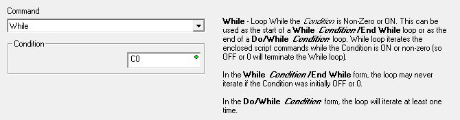
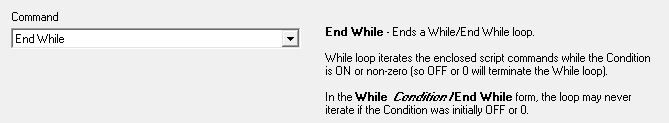
The While command either marks the end of a Do / While loop, or begins a While / End While loop where the commands between the While and End commands will be repeated as long as the condition in the While command is ON (if Boolean) or non-zero (if numeric). Because the While command that contains the check for the condition is at the beginning of the loop, the condition must be ON (if Boolean) or contain a non-zero value (if numeric) to get at least one pass through the commands in the While / End While loop.
The End While command marks the end of a While / End While Loop.
Importing and Exporting Script Steps
An alternate way of adding steps to an AXSCRIPT instruction is to import them from a text file. There are several sample files that ship with Do-more Designer that provide examples of the format for the different AXSCRIPT commands. These are located in the project's Examples\AXSCRIPT folder: for example: <Public Documents>\Do-more\Designer2_9\Projects\Examples\AXSCRIPT. The full path of the selected text file will be shown at the bottom left of the dialog.
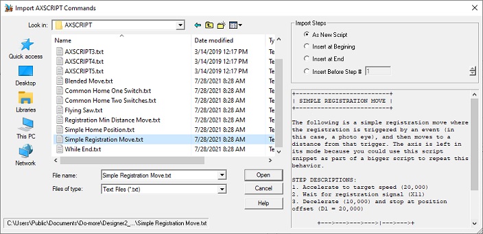
Click the Import button to open a File Open dialog where you can browse folders to select a file that contains the commands to import. Note: while selecting a file in the folder, if the highlighted file contains a description, the text of that description will appear in the bottom-right pane.
The Import Steps selections determine where the steps imported from the file will be placed in the table:
-
As New Script will remove any commands in the currently open table then add all of the commands found in the text file.
-
Insert at Beginning will add all of the commands found in the text file to the beginning of the currently open table; any existing steps will be shifted down in the table.
-
Insert at End will add the commands found in the text file to the end of the currently open table.
-
Insert before Step # will add the commands found in the text file before the specified step # in the currently open table; any existing steps after the step # will be shifted down in the table.
Click the Export button to open a File Save dialog where you select the folder and name of the file to store the exported commands. Once the export process has completed successfully, a dialog with the following options is shown:

-
Open AXSCRIPT Export File will open the exported text file in the default text editor (probably Notepad).
-
Explore AXSCRIPT Export File's Folder will open an Explorer dialog in the folder where the export file is stored.
Status Display
The status display of the AXSCRIPT instruction will show 4 steps with the current step being displayed with a blue background at the top of the list and the next three steps - if they exist - are shown below.
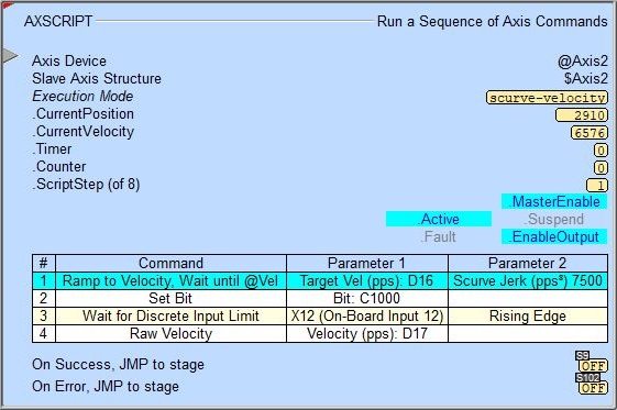
The red triangle in the upper left corner of the status display indicates this is a Fully Asynchronous instruction.
Execution Mode shows the current mode of the Axis (see a list of the possible execution mode values).
CurrentPosition / CurrentVelocity / Timer / Counter / ScriptStep (x of y) are the current values of these numeric fields from Axis' associated structure.
MasterEnable / Active / Suspend / Fault / EnableOutput are the current state of these Bit values from that Axis' associated structure.
A detailed description of the Numeric and Bit fields is available in AXCONFIG - Axis Configuration.
See Also
AXSETPROP - Axis Set Properties
AXRSTFAULT - Reset Axis Limit Fault
AXSCRIPT - Run a Sequence of Axis Commands
AXHOME - Axis Perform Home Search
AXPOSTRAP - Axis Move to Position Using Trapezoid
AXPOSSCRV - Axis Move to Position Using S-Curve
AXVEL - Axis Set Velocity Mode
AXGEAR - Axis Electronic Gearing
AXFOLLOW - Axis Position Following with Offset
AXCAM - Axis Electronic Camming
Related Topics
Example: Blended Move
The Axis position move instruction (AXPOSTRAP - Axis Move to Position Using Trapezoid arrives at its target position value AT a velocity of 0 (stopped). A prime example of a need to use the AXSCRIPT instruction is when your application needs the Axis to arrive at a target position value at a velocity that is NOT 0. This is sometimes referred to a "blended move".