Topic: DMD0407

TDODECFG - Deconfigure Table Driven Output
Once a TDOPLS - Load Programmable Limit Switch Table for Table Drive Output or TDOPreset - Load Preset Table for Table Drive Output has been enabled for a Table Driven Output, it will assume exclusive control of that output point. Use the Deconfigure Table Driven Output (TDODECFG) instruction to unload the Preset table or PLS table and relinquish control of the Table Driven Output.
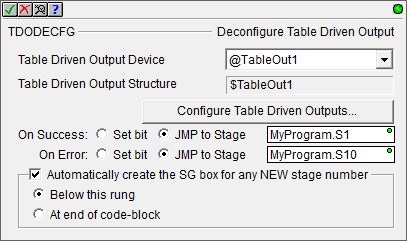
Table Driven Output Device selects which Table Driven Output this instruction will use. A Table Driven Output can only be selected for use by one Preset Table or Programmable Limit Switch at a time.
Table Driven Output Structure is the structure that is associated with this device. This structure is automatically created when the Table Driven Output itself is created.
Click the Configure Table Driven Outputs ... button to open the BRX Table Driven Outputs dialog in the System Configuration where the Table Driven Outputs are created and their High-Speed Outputs are selected.
The On Success and On Error parameters specify what action to perform when this instruction completes. You do not have to use the same type of selection for both On Success and On Error.
If the Set Bit selection is used for either On Success or On Error, the specified BIT location will be SET OFF when the instruction is first enabled and will remain OFF until the instruction completes. Once complete, the appropriate Success or Error bit location ON. The specified Bit location is enabled with a SET (Latch) operation meaning that it will remain ON even if the input logic for the instruction goes OFF.
If the JMP to Stage selection is used for either On Success or On Error the target Stage must be in the same Program code-block as this instruction, you cannot specify a target Stage that exists in a different Program code-block. When the operation finishes, the target Stage will be enabled the same way as a standalone Jump to Stage (JMP) instruction would do it. The JMP to Stage option will only be available if this instruction is placed in a Program code-block.
On Success selects which of the following actions to perform if the operation is successful:
- Enable SET Bit then specify any writable bit location.
- Enable JMP to Stage then specify any
Stage number from S0 to S127 in the current Program code-block.
On Error selects which of
the following actions to perform if the operation is unsuccessful:
- Enable SET Bit then specify writable bit location.
- Enable JMP to Stage then specify any Stage number from S0 to S127 in the current Program code-block.
If either the On Success or On Error selections are set to JMP to Stage, Automatically create the SG box for any NEW stage number will be enabled which will automatically create any target stage that does not already exist.
- Below this rung will create the new target stage on a new rung following this instruction.
- At end of code-block will create the new target stage as the last rung of this Program.
Display Status:
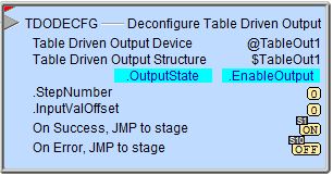
The red triangle in the upper left corner of the status display indicates this is a Fully Asynchronous instruction.
The gray triangle at the right end of the input leg indicates the input is edge-triggered, meaning this instruction will execute each time the input logic transitions from OFF to ON.
OutputState / EnableOutput - the current values of these numeric fields from Axis' associated structure.
See Also:
TDODECFG - Deconfigure Table Driven Output
TDOPLS - Load Programmable Limit Switch Table for Table Driven Output
TDOPreset - Load Preset Table for Table Driven Output
Related Topics:
BRX Pulse Width Modulated Outputs
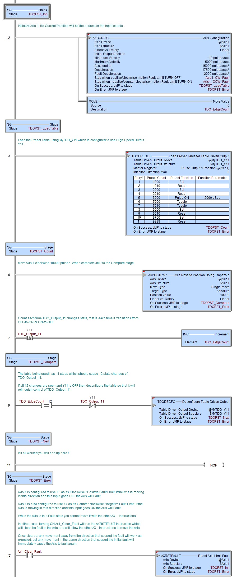
Example: