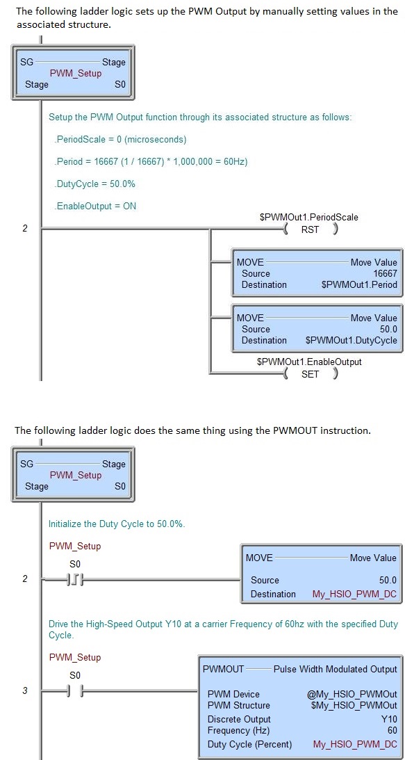
Topic: DMD0408

BRX Pulse Width Modulated Outputs
Pulse width modulation (PWM) is a technique in which a series of digital pulses is used to control an analog circuit. The length and frequency of these pulses determines the total power delivered to the output. PWM signals are most commonly used to control DC motors, but have many other applications ranging from controlling valves or pumps to adjusting the brightness of an LED.
The digital pulse train that makes up a PWM signal has a fixed frequency and varies the pulse width to alter the average power of the signal. The ratio of the pulse width to the period is referred to as the duty cycle of the signal. For example, if a PWM signal has a 10 ms period and its pulses are 2 ms long, that signal is said to have a 20 percent duty cycle. The image below shows four PWM signals with the same period but with different duty cycles:

Pulse-Width-Modulated Output Configuration
Setting up a PWM Output consists of creating a PWM Output Device, selecting the High-Speed output that the PWM Output device will use (either an on-board High-Speed output or a High-Speed I/O Module (BX-HSIO, BX-HSIO2 output), then manipulating the values in the associated structure to specify the operational characteristics of the output pulse train.
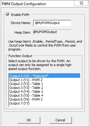
Device Name is the name given to this PWM High-Speed I/O output. This name will also be used as the name of the structure you will use to interact with this output in the ladder logic project. The device name can be 1 to 16 characters in length and consist of any combination of alphanumeric characters and underscores ('_', 'a-z', 'A-Z', 0-9), no spaces or punctuation marks are allowed, and must begin with a letter or an underscore.
Heap Item is the name of the associated structure that will be automatically created for this device.
Function Output selects which of the unused High-Speed I/O outputs the PWM function will use. As the outputs are selected you will see one of the following text appear to the right of a selection:
**CONFLICT** indicates the currently selected output is already being used by a PWM Output.
*Selected* indicates the currently selected output.
Pulse Output # indicates the output is already being used by an BRX Pulse Output / Axis.
PWM # indicates the output is already being used as another PWM Output.
Table # indicates the output is already being used as a BRX Table Driven Output.
After configuring the PWM Output you can control from ladder logic by using the PWMOUT - Pulse Width Modulated Output instruction, or by manually manipulating the members of the associated structure as described below.
PWM Output Structure:
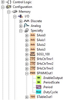
Each time a PWM Output is created, an associated structure is automatically created with the same name. This structure will contain member fields that are used in the Program to set the runtime configuration of the PWM Output. Each of these structures contain the following fields:
Set .EnableOutput ON to generate output pulses, set OFF to stop generating output pulses.
.PeriodScale selects the time base for the output pulses, 0 = Microseconds, 1 = Milliseconds.
.Period is the amount of time (in microseconds or milliseconds) for one complete pulse. This can be any positive constant value from 0 - 65535.
Note: remember, this value is NOT a frequency specified in Hz, this is the duration (in microseconds or milliseconds) of one pulse. Because Frequency and Period are reciprocals of each other, the following formulas can be used to convert a value specified in Hz to a Period value is milliseconds or microseconds:
Converting Hz to millisecond period = (1/ Hz) * 1000. For example: 60Hz = (1 / 60) * 1000 = 17 milliseconds.
Converting Hz to microsecond period = (1/ Hz) * 1,000,000. For example: 60Hz = (1 / 60) * 1,000,000 = 16667 microseconds.
.DutyCycle is the percentage of one period where the output is ON, during the remaining portion the output will be OFF. This can be any Real value between 0.0 and 100.0.
See Also:
PWMOUT - Pulse Width Modulated Output (this instruction uses a BRX PWM Output Structure)
TDODECONFIG - Deconfigure Table Driven Output
TDOPLS - Load Programmable Limit Switch Table for Table Driven Output
TDOPreset - Load Preset Table for Table Driven Output
Related Topics:
BX-HSIO1 / BX-HSIO2 High-Speed I/O Modules
BRX Pulse Width Modulated Outputs
Example: