Topic: DMD0411

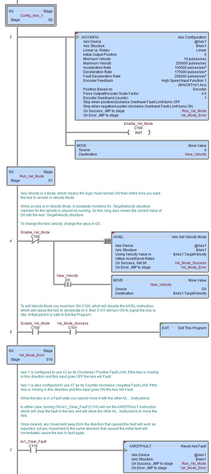
AXRSTFAULT - Reset Axis Fault
Note: this instruction can only be used with a BRX CPU !
The Reset Axis Fault (AXRSTFAULT) instruction is used to clear the fault in an Axis that has either reached one of the configured Over-travel Fault Limits while it was moving, or has had its MasterEnable manually turned OFF while the Axis was running, or an attempt has been made by an AXSCRIPT to execute a command that's illegal in the current state of the Axis. Note: the AXCONFIG - Axis Configuration instruction will also reset an Axis that is in a fault state.
When an Axis has faulted one the following Fault Codes will be in .Mode field of the Axis' associated structure:
65 (Positive Limit Fault) means the Fault Limit in the positive / clockwise has been reached.
66 (Negative Limit Fault) means the Fault Limit in the negative / counter-clockwise has been reached.
67 (Fault Both Limits) means the same input was specified as the Positive and Negative Fault Limit and it has been reached.
Note: if the fault was triggered by an over-travel limit, after this instruction has cleared the fault state, any attempt to move the Axis in the same direction that caused the fault will immediately generate another fault condition. Movement of the Axis in the opposite direction that caused the fault is permitted.
68 (Fault Master Enable) means the Axis' MasterEnable has been manually turned OFF.
69 (Fault-SCurve) means that while processing an AXSCRIPT - Run a Sequence of Axis Commands instruction, an attempt was made to run a Move to Absolute Position w/ S-Curve or a move to Relative Position w/ S-Curve at a point when the Axis was accelerating or decelerating (the Axis' .RateOfOChange is non-zero), or the target position is in the opposite direction the Axis is moving, or the Axis is at a velocity that would not allow the axis to get to the target position without over-shooting.
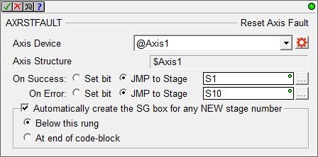
Axis Device selects which Axis this instruction will use - remember that Axis 0 is a virtual Axis meaning it will not generate pulses to physical outputs on the PLC.
Axis Structure displays the name of structure associated with this Axis. This structure was automatically created when the Axis itself was created.
Click the gear symbol at the right end of the Axis Device to open the BRX Axis / Pulse Outputs configuration dialog where the Axis' Pulse Output Mode is set and its High-Speed I/O outputs are selected.
The On Success and On Error parameters specify what action to perform when this instruction completes. You do not have to use the same type of selection for both On Success and On Error.
If the Set Bit selection is used for either On Success or On Error, the specified BIT location will be SET OFF when the instruction is first enabled and will remain OFF until the instruction completes. Once complete, the appropriate Success or Error bit location will be set ON. The specified Bit location is enabled with a SET (Latch) operation (not an OUT operation) meaning that it will remain ON even if this instruction's input logic goes OFF.
If the JMP to Stage selection is used for either On Success or On Error the target Stage must be in the same Program code-block as this instruction, you cannot specify a target Stage that exists in a different Program code-block. When the operation finishes, the target Stage will be enabled the same way as a standalone Jump to Stage (JMP) instruction would do it. The JMP to Stage option will only be selectable if this instruction is placed in a Program code-block.
On Success selects which of the following actions to perform if the operation is successful:
- Enable Set Bit then specify any writable bit location.
- Enable JMP to Stage then specify
any Stage number from S0 to S127 in the current Program code-block.
On Error selects which of
the following actions to perform if the operation is unsuccessful:
- Enable SET Bit then specify writable bit location.
- Enable JMP
to Stage then specify any Stage number
from S0 to S127 in the current Program code-block.
If either the On Success or On Error selections are set to JMP to Stage, Automatically create the SG box for any NEW stage number will be enabled which will automatically create any target stage that does not already exist.
- Below this rung will create the new target stage on a new rung following this instruction.
- At end of code-block will create the new target stage on the last rung of this Program.
Status Display
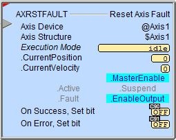
The red triangle in the upper left corner of the status display indicates this is a Fully Asynchronous instruction.
The gray triangle at the right end of the input leg indicates the input is edge-triggered, meaning this instruction will execute each time the input logic transitions from OFF to ON.
Execution Mode shows the current mode of the Axis (see a list of the possible execution mode values).
CurrentPosition / CurrentVelocity are the current values of these numeric fields from Axis' associated structure.
MasterEnable / Active / Suspend / Fault / EnableOutput are the current state of these Bit values from that Axis' associated structure.
A detailed description of the Numeric and Bit fields is available in AXCONFIG - Axis Configuration.
See Also
AXSETPROP - Axis Set Properties
AXRSTFAULT - Reset Axis Limit Fault
AXSCRIPT - Run a Sequence of Axis Commands
AXHOME - Axis Perform Home Search
AXPOSTRAP - Axis Move to Position Using Trapezoid
AXPOSSCRV - Axis Move to Position Using S-Curve
AXVEL - Axis Set Velocity Mode
AXGEAR - Axis Electronic Gearing
AXFOLLOW - Axis Position Following with Offset
AXCAM - Axis Electronic Camming
Related Topics
Example