Topic: DMD0398

AXPOSTRAP - Axis Move to Position Using Trapezoid
Note: this instruction can only be used with a BRX CPU !
The Axis Move to Position Using Trapezoid (AXPOSTRAP) instruction is used to move an Axis from its current position to a specified target position using the Axis' configured parameters which will yield a trapezoid velocity profile.
Axis Device selects which Axis this instruction will use - remember that Axis 0 is a virtual Axis meaning it will not generate pulses to physical outputs on the PLC.
Axis Structure displays the name of structure associated with this Axis. This structure was automatically created when the Axis itself was created.
Click the gear symbol at the right end of the Axis Device to open the BRX Axis / Pulse Outputs configuration dialog where the Axis' Pulse Output Mode is set and its High-Speed I/O outputs are selected.
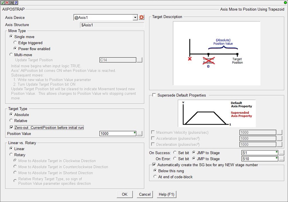
Move Type selects how the move to position operation will be initiated. This selection determines how the On Success and On Error parameters will operate.
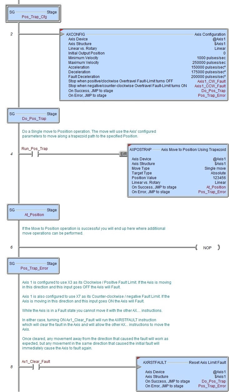
- Single Move is used when the Axis is expecting to perform a single move to position operation. The Axis' associated structure member AtPosition will turn ON when the Position Value is reached.
- Edge Triggered means the move to position operation will be performed each time the input transitions from OFF to ON. Once a move to position operation is in progress it can only be stopped by manually setting the Axis' MasterEnable to OFF, which will put the Axis into a Fault state.
- Power flow Enabled means the move to position operation will begin when the instruction's input logic transitions from OFF to ON and will continue to completion as long as the input remains ON. This selection has the benefit of being able to interrupt a move to position operation by setting the input state to OFF and NOT putting the Axis into a Fault state. If the input state goes OFF before the move is finished, the Axis will decelerate to 0 using its configured deceleration rate and perform the On Error condition described below.
- Edge Triggered means the move to position operation will be performed each time the input transitions from OFF to ON. Once a move to position operation is in progress it can only be stopped by manually setting the Axis' MasterEnable to OFF, which will put the Axis into a Fault state.
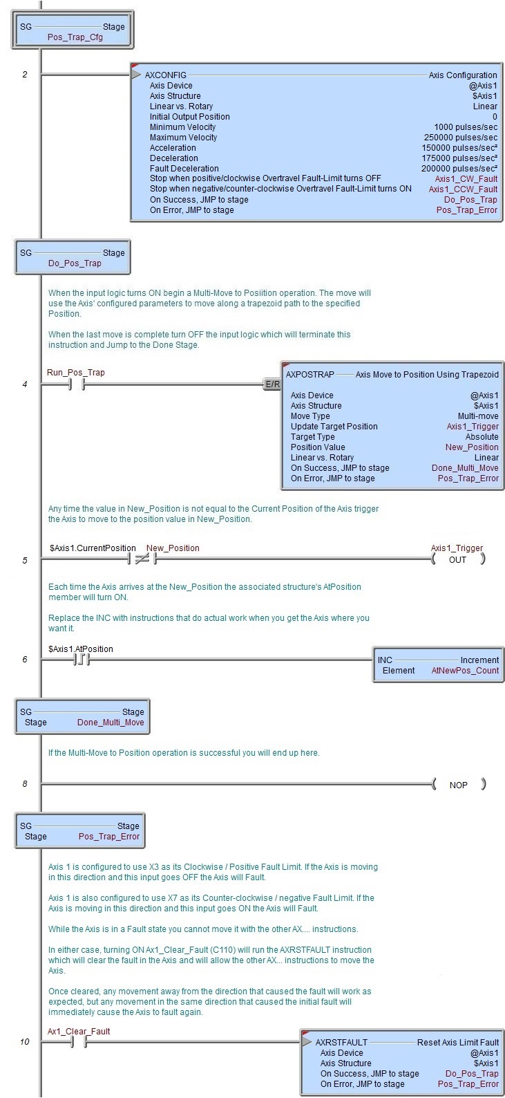
- Multi-move is used when the Axis is expecting to perform a sequence of move to position operations. The initial move operation will begin when the instruction's input logic transitions from OFF to ON. The Axis' associated structure member AtPosition will turn ON when the Position Value is reached. While the input logic remains ON the instruction will monitor the Update Target Position Bit location.
Update Target Position is a Bit location that is used to perform subsequent move to position operations. This is done by entering a new Position Value and turning this bit ON. The instruction will turn this Bit OFF to indicate that the Axis is moving toward the new Position Value. Any time after the instruction has turned this Bit OFF you can change the Position Value and set the Trigger Target Position back ON, which will cause the Axis to move toward the new Position Value. This allows the Axis to move toward a new Position Value without having to stop the current move to position operation.
Target Type specifies the target position value and whether that value is an absolute location or a location relative to the Axis' current position.
- Absolute moves are measured from Axis' zero position. When an Axis is initialized, its current position is set to 0. An absolute move to 10000 will generate 10000 pulses to move the Axis forward 10000 pulses. A subsequent absolute move to -10000 will generate 20000 pulses to move the Axis backward past 0 to the -10000 position. Executing an absolute move with a Position Value that is the same as the Axis' Current Position the Axis will not move as the absolute position is already reached.
- Relative moves are measured from the Axis' current position. When an Axis is initialized, its current position is set to 0. A relative move to 10000 will generate 10000 pulses to move the Axis forward 10000 pulses. A subsequent relative move to -10000 will generate 10000 pulses to move the Axis backward to the 0 position.
Enable the Zero Current Position Before Initial Move option to have the Axis set its Current Position value to zero before the move operation is executed.
If Single Move is selected for the Move Type this happens before the move to position operation begins. If Multi-move is selected for the Move Type this happens only once, when the Trigger Target Position input goes ON the first time, it does not happen between subsequent OFF to ON transitions of the Trigger Target Position.
Position Value is the target position the Axis will move to. The can be any constant value or any numeric location. Note: if Multi-move is selected at the Move Type this parameter should be a numeric memory location so the Position Value can be changed at runtime.
If the Axis is configured for Position Based on Encoder this value is the encoder count multiplied by the Axis' Pulse Output / Encoder Scale Factor.
If the Axis is configured for Position Based on Pulse Output, this value is the number of output pulses.
Linear vs Rotary selects specifies which type of action the pulse train will produce:
- Linear means the series of pulses will produce forward or backwards motion along a fixed linear path.
- Rotary means the series of pulses will produce motion that revolves on a circular path. Rotary mode needs to know which direction to rotate the Axis:
- Move to Absolute Target in Clockwise Direction will always generate pulses that will move the Axis in a clockwise direction.
- Move to Absolute Target in Counter-Clockwise Direction will always generate pulses that will move the Axis in a counter-clockwise direction.
- Move to Absolute Target in Shortest Direction will determine which direction is the shortest path to the Position then generate either clockwise or counter-clockwise pulses to move the Axis.
- Relative Rotary Target Type (Sign of Position Value Specifies Direction) means a positive position value will move the Axis in a clockwise direction; a negative position value will move the Axis in a counter-clockwise direction.
- Move to Absolute Target in Clockwise Direction will always generate pulses that will move the Axis in a clockwise direction.
Target Description will show a graphic that represents the type of positioning operation that will be performed by this instruction based on the current selections and parameters in the instruction.
Enable the Supersede Default Axis Properties option to have the Axis use the following parameters when performing the move operation instead of the current Axis configuration values. Note: this does NOT change these values in the Axis configuration, these parameters are only used during this one positioning operation. Use the Set Axis Properties (AXSETPROP) instruction to make global runtime changes to an Axis' configuration.
Maximum Velocity (pulses / second) is the fastest frequency of output pulses that will be generated during the move to position operation. This can be any positive constant from 10 to 2,000,000, or any numeric location with a value in that range. Note: only the BX-HSIO4 module can operate at velocities above 250KHz; attempting to use a velocity above 250KHz for an Axis that is using the on-board High-Speed I/O, or an Axis on a BX-HSIO1 or BX-HSIO2 module will result in a maximum velocity of that Axis still being 250KHz.
Acceleration (pulses / second2) - the rate at which the velocity will change when the Axis is ramping up from a slower pulse rate to a higher pulse rate, effectively it is how quickly to move from the current velocity to the maximum velocity. This can be any positive constant greater than 0 or any numeric location with a value in that range.
Deceleration (pulses / second2) - the rate at which the pulses will be generated when the axis is ramping down from a faster pulse rate to a slower pulse rate. This can be any positive constant greater than 0 or any numeric location with a value in that range.
The On Success and On Error parameters specify what action to perform when this instruction completes. You do not have to use the same type of selection for both On Success and On Error.
If the Set Bit selection is used for either On Success or On Error, the specified BIT location will be SET OFF when the instruction is first enabled and will remain OFF until the instruction completes. Once complete, the appropriate Success or Error bit location will be set ON. The specified Bit location is enabled with a SET (Latch) operation (not an OUT operation) meaning that it will remain ON even if this instruction's input logic goes OFF.
If the JMP to Stage selection is used for either On Success or On Error the target Stage must be in the same Program code-block as this instruction, you cannot specify a target Stage that exists in a different Program code-block. When the operation finishes, the target Stage will be enabled the same way as a standalone Jump to Stage (JMP) instruction would do it. The JMP to Stage option will only be selectable if this instruction is placed in a Program code-block.
On Success selects which of the following actions to perform if the operation is successful:
- Enable Set Bit then specify any writable bit location.
- Enable JMP to Stage then specify
any Stage number from S0 to S127 in the current Program code-block.
On Error selects which of
the following actions to perform if the operation is unsuccessful:
- Enable SET Bit then specify writable bit location.
- Enable JMP
to Stage then specify any Stage number
from S0 to S127 in the current Program code-block.
If either the On Success or On Error selections are set to JMP to Stage, Automatically create the SG box for any NEW stage number will be enabled which will automatically create any target stage that does not already exist.
- Below this rung will create the new target stage on a new rung following this instruction.
- At end of code-block will create the new target stage on the last rung of this Program.
Note: if this instruction is configured for Multi-move, the ON Success indication will turn ON after the input logic transitions from ON to OFF and the Axis' Current Velocity is at 0. When these conditions are met the Axis' Mode is "Idle". You should wait until the On Success indication turns ON before attempting to run any other Axis instruction.
Note: if this instruction is configured for Multi-move and the input logic turns OFF while a move operation is in progress, the ON Error indication will turn ON to indicate the Axis has an error. You should wait until the Axis associated structure member AtPosition turns ON before disabling this instruction.
Status Display
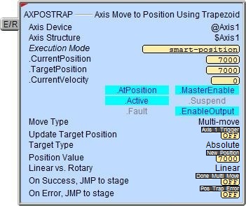
The red triangle in the upper left corner of the status display indicates this is a Fully Asynchronous instruction.
Execution Mode shows the current mode of the Axis (see a list of the possible execution mode values).
CurrentPosition / TargetPosition / CurrentVelocity are the current values of these numeric fields from Axis' associated structure.
AtPosition / MasterEnable / Active / Suspend / Fault / EnableOutput are the current state of these Bit values from that Axis' associated structure.
A detailed description of the Numeric and Bit fields is available in AXCONFIG - Axis Configuration.
See Also
AXSETPROP - Axis Set Properties
AXRSTFAULT - Reset Axis Limit Fault
AXSCRIPT - Run a Sequence of Axis Commands
AXHOME - Axis Perform Home Search
AXPOSTRAP - Axis Move to Position Using Trapezoid
AXPOSSCRV - Axis Move to Position Using S-Curve
AXVEL - Axis Set Velocity Mode
AXGEAR - Axis Electronic Gearing
AXFOLLOW - Axis Position Following with Offset
AXCAM - Axis Electronic Camming
Related Topics
Single Move Example
Multi-move Example