Topic: DMD0401

AXVEL - Axis Set Velocity Mode
Note: this instruction can only be used with a BRX CPU !
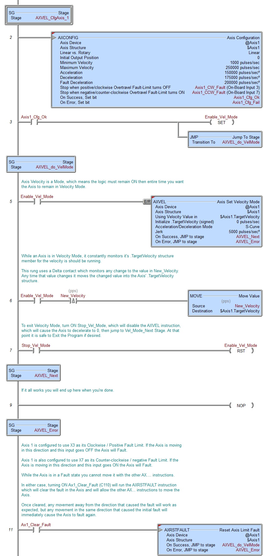
The Axis Set Velocity Mode (AXVEL) instruction is used to put an Axis into an operational mode where its movement is controlled by velocity rather than position.
The ladder logic input to this instruction is an Enable / Reset, which means when the input logic turns ON the Axis will accelerate to the Axis structure's TargetVelocity value, and when the input logic turns OFF the Axis will decelerate to a velocity of 0, at that point the instruction will end. While this instruction is enabled, the Axis' associated structure member TargetVelocity is live, meaning that any time this value changes the Axis will respond to that change by accelerating or decelerating as needed. Note: if the structure's TargetVelocity location is non-zero when the instruction is enabled, the Axis will immediately begin accelerating toward that TargetVelocity value.
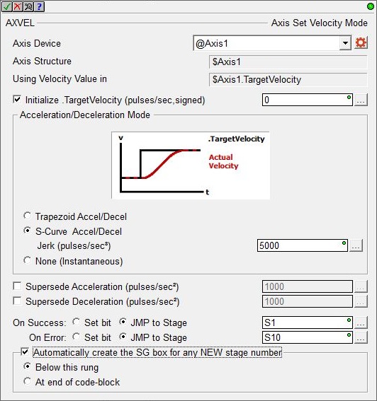
Axis Device selects which Axis this instruction will use - remember that Axis 0 is a virtual Axis meaning it will not generate pulses to physical outputs on the PLC.
Axis Structure displays the name of structure associated with this Axis. This structure was automatically created when the Axis itself was created.
Using Velocity Value in shows the Axis' structure member that contains the Velocity parameter that is being manipulated by this instruction.
Click the gear symbol at the right end of the Axis Device to open the BRX Axis / Pulse Outputs configuration dialog where the Axis' Pulse Output Mode is set and its High-Speed I/O outputs are selected.
Enable the Initialize Target Velocity (Signed) the option to set the velocity of the Axis when this instruction is enabled. A non-zero value will cause the Axis to begin moving at the specified velocity as soon as this instruction is enabled. This value can be any constant between -2,000,000 and 2000,000 or any numeric location containing a value in that range. The sign of the value will indicate the direction of travel: positive numbers will cause the Axis to move clockwise, negative numbers will cause the Axis to move counter-clockwise. Any value that is below the Axis' Configured Minimum Velocity will result in the Axis Minimum Velocity being used. Note: only the BX-HSIO4 module can operate at velocities above 250KHz; attempting to use a velocity above 250KHz for an Axis that is using the on-board High-Speed I/O, or an Axis on a BX-HSIO1 or BX-HSIO2 module will result in a maximum velocity of that Axis still being 250KHz.
Acceleration / Deceleration Mode specifies what level of Acceleration / Deceleration to use when the Axis is changing to a new Target Velocity. The graphic will change with the selection to display what the velocity curve will look like for that selection.
- Trapezoid Accel / Decel means the Axis will ramp from the Current Velocity to the new Target Velocity value using the Axis' currently configured Acceleration and Deceleration values which results in a trapezoid velocity path.
- S-Curve Accel / Decel means the Axis will ramp from the Current Velocity to the new Target Velocity value using the Axis' currently configured Acceleration and Deceleration values in addition to the following Jerk parameter which results in an S-Curve velocity path.
- Whereas the Acceleration and Deceleration values specify how quickly the Axis is allowed to reach maximum velocity, the Jerk (pulses / sec3) parameter specifies how quickly the Axis is allowed to achieve maximum Acceleration and Deceleration (larger values reach the Max Accel / Max Decel values more quickly). This can be any positive constant greater than 0 or any numeric location with a value in that range.
- Whereas the Acceleration and Deceleration values specify how quickly the Axis is allowed to reach maximum velocity, the Jerk (pulses / sec3) parameter specifies how quickly the Axis is allowed to achieve maximum Acceleration and Deceleration (larger values reach the Max Accel / Max Decel values more quickly). This can be any positive constant greater than 0 or any numeric location with a value in that range.
- None (Instantaneous) means the Axis will immediately begin moving at the specified Target Velocity value; there is no ramp up or ramp down to the new velocity.
When the Axis is ramping up from a slower velocity to a higher velocity use the specified valueSupersede Acceleration (pulses / second2) instead of the Axis' configured acceleration. This can be any positive constant greater than 0 or any numeric location with a value in that range.
When the Axis is ramping down from a faster velocity to a slower velocity use the specified value Supersede Deceleration (pulses / second2) instead of the Axis' configured deceleration. This can be any positive constant greater than 0 or any numeric location with a value in that range.
Note: Selecting to supersede these values in this instruction does NOT change the Axis configuration, these parameters are only used while this particular velocity mode instruction is enabled. Use the Set Axis Properties (AXSETPROP) instruction to make global runtime changes to an Axis' configuration if that is required.
This instruction puts the specified Axis into an operational mode - as opposed to performing a single operation. Because this is a mode change operation, ON Success is defined as getting the Axis into this mode and back out of this mode with no errors or faults.
When the input logic turns ON, the On Error indication will turn ON if there is a problem getting the Axis into the this operational mode. It will remain OFF if the mode change is successful.
Once the Axis is in this mode, the On Success indication will turn ON after the input logic turns OFF and the Axis' decelerates to 0 (the Current Velocity reaches 0). At this point the Axis' Mode will be "Idle". Once the input logic turns OFF and the deceleration phase begins, if the input logic turns back ON while the Axis is still decelerating, the Axis will NOT start moving again. You must wait until the On Success indication turns ON - the Axis must be "Idle" - before attempting to run any other Axis instruction.
The On Success and On Error parameters specify what action to perform when this instruction completes. You do not have to use the same type of selection for both On Success and On Error.
If the Set Bit selection is used for either On Success or On Error, the specified BIT location will be SET OFF when the instruction is first enabled and will remain OFF until the instruction completes. Once complete, the appropriate Success or Error bit location will be set ON. The specified Bit location is enabled with a SET (Latch) operation not an (OUT) operation meaning that it will remain ON even if this instruction's input logic goes OFF.
If the JMP to Stage selection is used for either On Success or On Error the target Stage must be in the same Program code-block as this instruction, you cannot specify a target Stage that exists in a different Program code-block. When the operation finishes, the target Stage will be enabled the same way as a standalone Jump to Stage (JMP) instruction would do it. The JMP to Stage option will only be selectable if this instruction is placed in a Program code-block.
On Success selects which of the following actions to perform if the operation is successful:
- Enable Set Bit then specify any writable bit location.
- Enable JMP to Stage then specify any Stage number from S0 to S127
in the current Program code-block.
On Error selects which of the following actions to perform if the operation is unsuccessful:
- Enable SET Bit then specify writable bit location.
- Enable JMP to Stage then specify any Stage number from S0 to S127
in the current Program code-block.
If either the On Success or On Error selections are set to JMP to Stage, Automatically create the SG box for any NEW stage number will be enabled which will automatically create any target stage that does not already exist.
- Below this rung will create the new target stage on a new rung following this instruction.
- At end of code-block will create the new target stage as the last rung of this Program.
Status Display
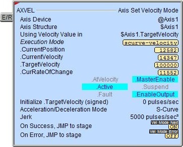
The red triangle in the upper left corner of the status display indicates this is a Fully Asynchronous instruction.
Execution Mode shows the current mode of the Axis (see a list of the possible execution mode values).
CurrentPosition / CurrentVelocity / TargetVelocity / CurRateOfChange are the current values of these numeric fields from Axis' associated structure.
AtVelocity / MasterEnable / Active / Suspend / Fault / EnableOutput are the current state of these Bit values from that Axis' associated structure.
A detailed description of the Numeric and Bit fields is available in AXCONFIG - Axis Configuration.
See Also
AXSETPROP - Axis Set Properties
AXRSTFAULT - Reset Axis Limit Fault
AXSCRIPT - Run a Sequence of Axis Commands
AXHOME - Axis Perform Home Search
AXPOSTRAP - Axis Move to Position Using Trapezoid
AXPOSSCRV - Axis Move to Position Using S-Curve
AXVEL - Axis Set Velocity Mode
AXGEAR - Axis Electronic Gearing
AXFOLLOW - Axis Position Following with Offset
AXCAM - Axis Electronic Camming
Related Topics
Example