Topic: DMD0409

BRX Counter / Timer / Pulse Catch Functions
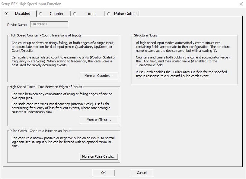
The High-Speed inputs of properly-equipped BRX CPUs, and the inputs on the BRX HSIO modules BX-HSIO1 and BX-HSIO2 can operate at frequencies up to 250kHz - BX-HSIO4 can operate at frequencies up to 2MHz. To manage input pulses that operate at these high rates, the BRX PLCs can be configured to count, time, or catch theses pulses and generate responses to the input pulses as shown below:
High Speed Counters will count OFF-to-ON and / or ON-to-OFF transitions of pulses on single input, or use two inputs for quadrature counting. Optionally, it can accumulate the count values and scale the incoming pulses as a position value or a pulse rate.
High Speed Timers will measure time between successive pulses on a single input, or the time between pulses on two different inputs, or the duration of input pulses. Optionally the accumulated time can be scaled to a pulse rate. Timing between pulses will usually yield a better result than using a high speed counters and scaling pulse counts from slow speed pulses.
High Speed Pulse Catch will generate an output that can be seen by the PLC scan in response to input pulses that are too fast to reliably be seen otherwise. The output can be configured to ON for one PLC scan or ON for a fixed number of milliseconds.
High Speed Counters
High Speed Counters will count OFF-to-ON and / or ON-to-OFF transitions of input pulses on single input, or use two inputs for quadrature counting. Optionally, it can accumulate the count values and scale the incoming pulses as a position value or a pulse rate.
Device Name is the name given to this High-Speed Counter or Timer function. This name will also be used as the name of the structure you will use to interact with this counter function in the ladder logic project. The device name can be 1 to 16 characters in length and consist of any combination of alphanumeric characters and underscores ('_', 'a-z', 'A-Z', 0-9), no spaces or punctuation marks are allowed, and must begin with a letter or an underscore.
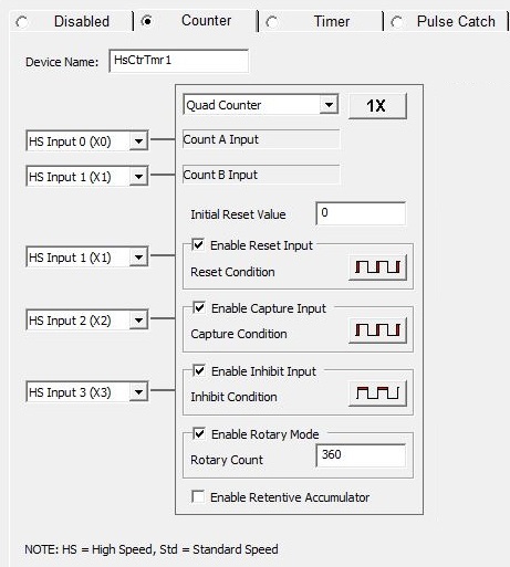
Counter Type
Specifies what type of input will be considered a pulse that can be counted, and how those pulses are to be used in the counting function. The number of pulses that have been received on the counter input(s) is stored in the structure field $DeviceName.Acc.
Up Counter increments the count on each single pulse.
Down Counter decrements the count on each single pulse.
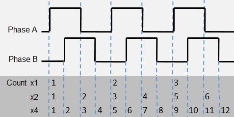
Quad Counter increments and decrements a count based on a quadrature pulse train, typically from an incremental encoder. The most common type of incremental encoder uses two channels (A and B) to sense position. Using two code tracks with sectors positioned 90 degrees out of phase, the two channels of the quadrature encoder indicate both position and direction of rotation. If A is received before B the encoder is rotating in a clockwise direction. If B is received before A the encoder is rotating in a counter-clockwise direction. By monitoring both the number of pulses and the relative phase of signals A and B, you can track both the position and direction of rotation. Some quadrature encoders also include a third output channel, called a zero or index or reference signal, which supplies a single pulse per revolution for precise determination of a reference position.
Count Multiplier (for Quad Counter) specifies how many counts to record for the input pulses received. Clicking the button cycles through the following three selections:
1X counts leading edge of pulse on Count Input A.
2X counts leading and falling edges of pulse on Count Input A.
4X counts leading and falling edges of pulses on both Count Input A and Count Input B.
Note: selecting 2X or 4X count multiplier does not change the maximum frequency of the input. In quadrature mode the on-board HSIO, the BX-HSIO1, and the BX-HSIO2 have a maximum input frequency of 250KHz but can count individual edges up to 1MHz; the BX-HSIO4 has a maximum input frequency of 2MHz but can count individual edges up to 8MHz.
Bidirectional Counter increments and decrements a count of single pulses on one input based on the high / low level of a second input.
Up / Down Counter increments a count of single pulses on one input and decrements the same count of single pulses on a second input.
Count A Input will select which of the High-Speed discrete inputs to use as the count input.
Count B Input for Counter Types that require two input signals, specify which of the High-Speed discrete inputs to use as the second input.
Initial Reset Value is the value that will be loaded into the Accumulator of the counter when a reset of the Counter occurs. It must be a value between -2,147,483,648 and +2,147,483,647.
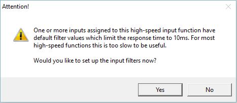
Note: the default Input Filter value of 10ms (25Hz / 750000 clocks) is not an appropriate value when the High-Speed I/O inputs are used for high-speed input devices like encoders. You will want to change the Input Filter value to a faster response time (lower filter value) to allow those high speed devices to work as expected. Do-more Designer will display the following message box any time one of the High-Speed I/O inputs is selected for use in one of the High-Speed I/O functions without changing the default filter time.
Reset Input
Optionally specify one of the High-Speed discrete inputs that will stop the current count operation and the current count value will be cleared or set to the Initial Reset Value. If the Counter Type is Quad Counter this is typically the zero or index input from an encoder or a reference signal.
Enable Reset Input specifies which of the High-Speed discrete inputs to use as the hardware reset input. See the note above concerning the default Input Filter value.
Reset Condition configures the reset to execute either on the rising edge, falling edge, high level or low level of the specified input. Clicking the button cycles through the edge and level selections.
The edge reset selections set the current count to the Initial Reset Value on the specified edge (rising or falling) of the reset pulse.
The level reset selections reset the current count to the Initial Reset Value and holds it there as long as the reset input is held high or low (depending on the configuration). When the reset pulse is not active, the count resumes.
In addition to this hardware reset input, there is a software reset available that is performed through the structure fields named $DeviceName.EdgeReset or the $DeviceName.LevelReset. Any time the hardware level reset input is ON or the software level reset structure field is ON, the structure field $DeviceName.AtResetValue will be ON.
Capture Count Input
Optionally specify one of the High-Speed discrete inputs that will capture the current count value when the specified input signal changes states. This Count Capture operation must be enabled by turning ON the capture enable structure member ($DeviceName.EnableCapture). At that point, when the required input signal is received, the current count value is copied to $DeviceName.CapturedValue and $DeviceName.CountCaptured is turned ON. To repeat the capture operation, the capture enable bit $DeviceName.EnableCapture must be turned OFF, then turned back ON as described earlier.
Enable Capture Input specifies which of the High-Speed discrete inputs to use as the capture input. See the note above concerning the default Input Filter value.
Capture Condition configures the capture to execute either on the rising edge or falling edge of the Enable Capture Input. Clicking the button cycles through the edge selections.
To perform a capture using the Capture Count function, do the following:
Enable the capture function by setting ON the structure member $DeviceName.EnableCapture.
When the capture signal is seen on the Capture input, the current pulse count value in the structure field $DeviceName.Acc is copied to the structure field $DeviceName.CapturedValue and the structure field $DeviceName.CountCaptured is set ON to indicate the capture operation is complete.
To repeat the count capture function the capture enable bit $DeviceName.EnableCapture must be set OFF than back ON as described above.
Inhibit Count Input
Optionally specify one of the High-Speed discrete inputs that will cause the counter to stop counting input pulses. Any time the Inhibit input is ON, the current pulse count value is maintained and any new pulses are not counted. When the Inhibit input is no longer active new pulses will be counted.
Enable Inhibit Input specifies which of the High-Speed discrete inputs to use as the inhibit input. See the note above concerning the default Input Filter value.
Inhibit Condition configures the inhibit to execute either in the high state or low state of input. Clicking the button cycles through the level selections.
Rotary Mode (only available for Quad, Bi-Directional, and Up / Down Counters)
Input pulses that originate from a rotary source are expected to generate count values that wrap at a certain count value. One positive pulse at the maximum value will wrap the Current Count value to 0. One negative pulse at 0 will wrap the Current Count to the maximum value.
Enable Rotary Mode sets the input pulse counter into rotary mode.
Rotary Count specifies the total number of counts in the rotary range. The range of count values will be 0 to (Rotary Count - 1).
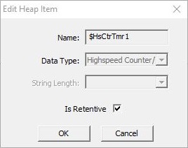
Enable Retentive Accumulator
Optionally make the current count value in the accumulator retentive, meaning that it will retains it's current value through a loss of system power. For this option to work correctly the high speed counter's associated structure also must be marked as retentive in the Memory Configuration as shown below:
Enable Position or Rate Scaling
The BRX CPUs can optionally convert the pulse count into more useful forms. This scaling function typically converts the pulse count into a distance or position through Position Scaling, or into a speed, flow rate, or velocity through Rate Scaling. When scaling is enabled, each time a new scaled value is computed it will be placed in the $DeviceName.ScaledValue structure field.
Converts "raw" pulse count values to "engineering units" of distance using linear interpolation.
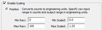
The user provides Min Raw / Max Raw and Min Scaled/ Max Scaled and the scaling function will use those values and the current pulse count to derive a distance or position value.
Rate Scaling
Converts "raw" pulse count values to "engineering units" by sampling the accumulated count value over a period of time. Rate scaling of a pulse train is preferred over Interval Scaling of the time between pulses for frequencies over 5 KHz. Because this form of scaling renders a velocity, the result of the scaling operation will be some distance unit (e.g. inches, feet, revolutions, etc.) per some time unit (seconds, minutes, hours).
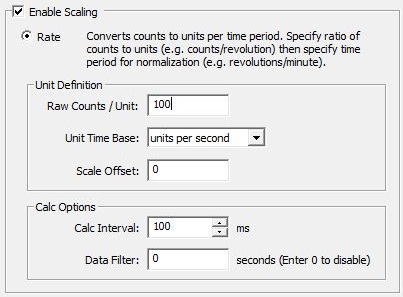
The user provides the Raw Counts / Unit of time, the Unit Time Base (per Second, per Minute, per Hour), a Scale Offset, and optionally a Calculation Interval and Data Filter for smoothing.
Raw Counts / Unit is the number of counts per velocity unit.
Unit Time Base is the time base for the unit being measured.
Scale Offset is the constant amount to be added to the calculated value.
Calc Interval specifies how often (in milliseconds) a new rate scaled value should be calculated. This value should be set only as short as the fastest rate at which a new scaled value is required for the application.
Data Filter specifies the number of seconds over which the calculated scaled values will be averaged, providing a smoothing affect in the rate scaled value.
Rate Scale Example #1
An RPM (revolutions per minute) value is needed for a motor that has an 800-ppr (pulses per revolution) encoder that is wired to the High-Speed I/O inputs on a BRX CPU.
The encoder yields 800 pulses in 1 revolution. So if it makes 1 revolution in 1 minute, that would yield 800 pulses in 1 minute's time. So if the BRX CPU sees 800 pulses in the time span of 1 minute, that would be 1 RPM. So the Raw Counts / Unit is equal to 800 (meaning 800 pulses per minute = 1 RPM).
Since the desired unit is RPM (revolutions per minute) a Unit Time Base of Minutes is selected.
Scale Offset is zero because when there are no pulses being generated we want the value to be 0 RPM.
Rate Scale Example #2
A FPS (feet per second) value is needed for a conveyor belt that is driven by a roller with a diameter of 10 inches. The same 800-ppr encoder is attached to the roller.
To figure out the Raw Counts / Unit value, the number of pulses received when the conveyor belt moves 1 foot must first be calculated. Since the roller is 10 inches in diameter and the belt is wrapped around it, the circumference is the diameter multiplied by PI (10 inches x 3.14159) which is 31.4159 inches.
So when the roller rotates one full turn it has moved the conveyor 31.4159 inches, and also moved the encoder 800 pulses, meaning that 800 pulses = 31.4159 inches of belt movement. Since the desired unit is feet per second and there are 12 inches per foot, then 31.4159 inches / 12 in / ft = 2.618 feet. 1 turn of the roller would also generate 800 pulses, so 800 pulses = 2.618 feet of belt movement.
To compute the number of pulses per foot, 800 pulses per revolution / 2.618 feet per revolution = 305.577 pulses per foot. So the value for Raw Counts / Unit is 305.577. The High-Speed I/O input cannot detect actually a fraction of a pulse, but a fractional value can be used in the calculation to help get the most accurate scaled value.
Since the desired unit is fps (feet per Second) a Unit Time Base of Seconds is selected.
Scale Offset is zero because when there are no pulses being generated when the pulley isn't moving we want the value to be 0 FPS.
High Speed COUNTER Structure
Each time a Counter device is created an associated structure is automatically created using the same name.
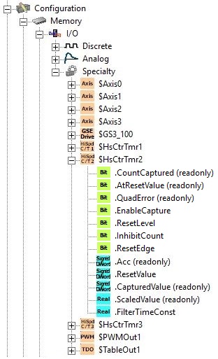
.CountCaptured (read only) (if capture input selected): this Bit will be ON after the Count Capture process has completed.
.AtResetValue (read only): this Bit will be ON any time the Current Count is at the specified Reset Value.
.QuadError (read only): if configured for a Quadrature input and pulses are received on both inputs at the same time this bit will be ON. This can happen if the physical input is NOT a quadrature signal, and if the frequency of the input pulses are too fast. This bit will be automatically reset any time the counter is reset.
.EnableCapture (if capture input selected): set this Bit ON to have the Current Count value stored in the CapturedValue register.
.ResetLevel: set this Bit ON to Reset the Current Count value to the specified Reset Value and remain at the Reset Value until this Bit is turned OFF, once OFF counting incoming pulses will continue
.InhibitCount: when this Bit is ON any incoming pulses will not be counted.
.ResetEdge: set this bit ON to Reset the Current Count value to the specified Reset Value then continue to count incoming pulses.
.Acc (read only)is the Current Count value is stored here.
.ResetValue: any time a Reset operation is performed the Current Count value will be set to this value.
.CapturedValue (read only) (if capture input selected) will contain the last count value that was captured.
.ScaledValue (read only) (if scaling enabled): if the input is position or rate scaled, the scaled value will be placed here.
.FilterTimeConst (if scaling enabled) - this is how often (in seconds) the scaled value is calculated. A value of 0.0 disables the Filter.
High Speed Pulse Timing (Edge Timing / Dual Edge Timing)
As an alternative to counting input pulses, the High-Speed discrete inputs can be configured to measure the amount of time between pulses. When the desired result is a scaled value representing a speed or rate, this can be a better option for pulse rates below 5 KHz than using one of the pulse counting selections.
Device Name is the name given to this High-Speed Edge Timer function. This name will also be used as the name of the structure you will use to interact with this edge timer function in the ladder logic project. The device name can be 1 to 16 characters in length and consist of any combination of alphanumeric characters and underscores ('_', 'a-z', 'A-Z', 0-9), no spaces or punctuation marks are allowed, and must begin with a letter or an underscore.
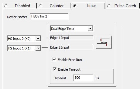
Edge Timer Type
Specifies how the edge -to- edge timing will be measured and how that time will be used in the scaling function.
Edge Timer measures the time from the edge of a single pulse to the same edge on the subsequent pulse.
Dual Edge Timer measures the time from an edge of a single pulse in one discrete input to the same edge of a single pulse on a second discrete input.
Edge 1 Input selects which of the High-Speed discrete inputs to use as the timer input.
Dual Edge Timers requires a second input, Edge 2 Input selects which of the BRX High-Speed discrete inputs to use as the second input.
Edge Selector specifies whether the rising edge -to- rising edge, rising edge -to- falling edge, falling edge -to- rising edge, or falling edge -to- falling edge is monitored for the edge timing function. Clicking the button cycles through the edge selections.
Enabling Enable Free Run causes the edge timer to automatically re-arm itself after each timing measurement. If unchecked, the edge timer must be manually armed for each measurement.
Enable Timeout: enabling this option and entering a timeout value (in microseconds) keeps the edge timer from "getting stuck" waiting for the second edge to signal the end of the timing. When the first edge is detected, if the second edge is not received before the Timeout period expires, the $DeviceName.Timeout structure field is set ON. The Timeout value must be between 1 and 2,147,483,647 microseconds.
To perform a capture using the Edge Timer or Dual Edge Timer function, do the following:
Enable the Timer by setting the structure field $DeviceName.EnableTimer ON.
Once the first pulse has been detected on the first input, the structure field $DeviceName.TimerStarted is set ON and time begins to accumulate in the structure
field $DeviceName.Acc.
Once the second edge is detected, the structure field $DeviceName.TimerComplete is set ON and the measured time is copied into the structure field $DeviceName.LastTime, and if Interval Scaling is enabled the new scaled value is calculated and copied into the structure field $DeviceName.ScaledValue.
If Timeout is enabled and the second edge is not detected before the Timeout value is reached, the structure field $DeviceName.Timeout is set ON.
If Free Run is enabled the Timer automatically re-arms itself, if Free Run is not enabled, the Timer must be manually re-enabled to measure again.
Enable Interval Scaling
Interval scaling uses the time between input pulses to calculate the frequency of the input pulses, then normalizes that frequency to a desired time base. Interval scaling is typically used for units of speed, flow, velocity, etc., and is preferred over Rate Scaling for input pulse frequencies lower than 5KHz. Because this form of scaling renders a velocity, the result of the scaling operation will be some distance unit (e.g. inches, feet, revolutions, etc.) per some time unit (seconds, minutes, hours).
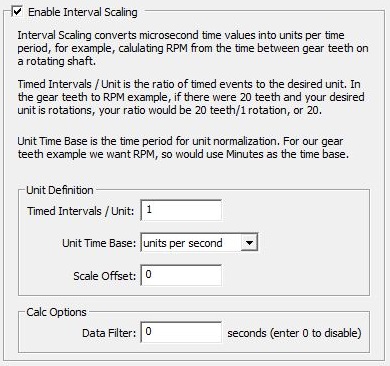
The interval scaling operation requires the following three parameters:
Timed Intervals / Unit is the number of pulses over a certain period, for example, the number of teeth on a gear, or the number of index marks on a belt.
Unit Time Base is the time unit you want the interval normalized to, either units per Second, Minute or Hour.
Scale Offset is a fixed value to add to each frequency calculation.
You can optionally enable a Data Filter that will perform a rolling average of the Interval Scaled values over the time ( in seconds ) specified for the Data Filter. A value of 0 disables the use of the Data Filter.
Interval Scale Example #1
A value for the RPM (revolutions per minute) is needed for a motor whose encoder is wired to the High-Speed I/O Inputs on a BRX CPU. The encoder produces 800 pulses per revolution.
The encoder yields 800 pulses in 1 revolution. Each time it makes 1 revolution in 1 minute, that would yield 800 pulses in 1 minute's time. So if the input sees 800 pulses in the time span of 1 minute, that would be 1 RPM. So the Time Intervals / Unit is equal to 800 (meaning 800 pulses per minute = 1 RPM).
Since the desired unit is RPM (revolutions per minute) a Unit Time Base of Minutes is selected.
Scale Offset is zero because when there are no pulses being generated we want the value to be 0 RPM.
Interval Scale Example #2
A value for the FPS (feet per second) is needed for a conveyor belt. This conveyor belt is driven by a roller that is 10 inches in diameter and the same 800 ppr encoder is attached to the roller.
To figure out the Time Intervals / Unitvalue, the number of pulses received when the conveyor belt moves 1 foot must first be calculated. Since the roller is 10 inches in diameter and the belt is wrapped around it, the circumference must be calculated first. This is the diameter of the wheel multiplied by pi. 10 inches x 3.14159 = 31.4159 inches.
So when the roller rotates one full turn it has moved the conveyor 31.4159 inches, and also moved the encoder 800 pulses, meaning that 800 pulses = 31.4159 inches of belt movement. Since the desired unit is feet per second and there are 12 inches per foot, then 31.4159 inches / 12 in per ft = 2.618 feet. This means when the roller turns 1 full turn, it has moved the belt 2.618 feet meaning that 800 pulses = 2.618 feet of belt movement.
To compute the number of pulses per foot: 800 pulses / 2.618 feet = 305.577 pulses per foot. So the value for Time Intervals / Unit is 305.577. The High-Speed I/O input cannot detect actually a fraction of a pulse, but a fractional value can be used in the calculation to help get the most accurate scaled value.
Since the desired unit is fps (feet per second) a Unit Time Base of Seconds is selected.
Scale Offset is zero because when there are no pulses being generated when the pulley isn't moving we want the value to be 0 FPS.
High Speed TIMER Structure
Each time an Edge Timer device is created an associated structure is automatically created using the same name.
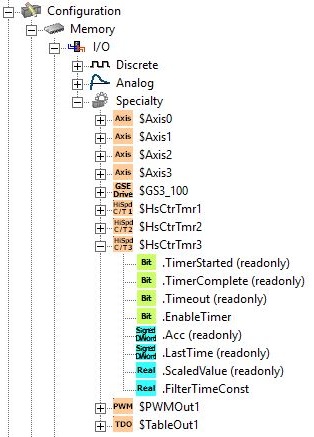
.TimerStarted (read only): this Bit will be ON when the first input pulse is received.
.TimerComplete (read only): this Bit will be ON when the successive input pulse is received.
.Timeout (read only): this Bit will be ON if the Time between input pulses exceeds the preconfigured Timeout Value.
.EnableTimer: set the Bit ON to begin an edge timing operation.
.Acc (read only) is the current amount of time since the last input pulse was received.
.LastTime (read only) is the amount of time between the last two input pulses.
.ScaledValue (read only): if the input count is interval scaled, the scaled value will be placed here.
.FilterTimeConst is how often (in seconds) the scaled value is calculated. A value of 0.0 disables the Filter.
High Speed Pulse Catch
The High Speed Pulse Catch will generate an output that can be seen by the PLC scan in response to input pulses that are too fast to reliably be seen otherwise. The output can be ON for one PLC scan, or ON for a fixed number of milliseconds. Once the Pulse Catch has been configured, it's operation is completely automatic; it is active any time the PLC is in RUN mode. The associated structure member .PulseCatchOut will come ON each time a Pulse Catch event is processed, and .Output time will show the amount of time(in milliseconds) that .PulseCatchOut will remain ON.
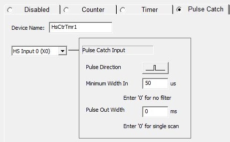
Device Name is the name given to this High-Speed Counter or Timer function. This name will also be used as the name of the structure you will use to interact with this counter function in the ladder logic project. The device name can be 1 to 16 characters in length and consist of any combination of alphanumeric characters and underscores ('_', 'a-z', 'A-Z', 0-9), no spaces or punctuation marks are allowed, and must begin with a letter or an underscore.
Pulse Catch Input selects which of the High-Speed inputs to use. Note: although you can select any of the on-board discrete inputs, only the first 10 inputs of properly-equipped BRX CPUs are high speed. All of the inputs on th HSIO modules are High-Speed
The Pulse Direction button specifies whether to monitored the input for positive pulses or negative pulses. Clicking the button cycles through the possible selections.
Minimum Width In specifies the minimum pulse width (in microseconds) that will generate a Pulse Catch event.
Pulse Out Width specifies how long the generated output (the structure member .PulseCatchOut) will be ON each time a Pulse Catch event is generated. A value of 0 means the output will be ON for one complete PLC scan. Any other positive value means the output will be ON for that number of milliseconds. The structure member .OutputTime contains the amount of time(in milliseconds) remaining for the output to be ON.
High Speed Pulse Catch Structure
Each time a Pulse Catch device is created an associated structure is automatically created using the same name.
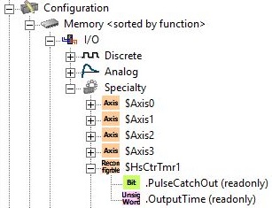
.PulseCatchOut (read only) this Bit will turn ON when the input pulse is seen, and will remain ON for one PLC scan or for the Output Time depending on how the Pulse Catch is configured.
.OutputTime (read only) contains the number of milliseconds the Pulse Catch output will remain ON
See Also:
BX-HSIO1 / BX-HSIO2 High-Speed I/O Modules
BRX Timer / Counter / Pulse Catch Functions
Related Topics:
BRX Pulse Width Modulated Outputs