Topic: DMD0405

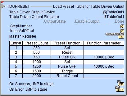
TDOPreset - Load Preset Table for Table Driven Output
A Load Preset Table for Table Driven Output (TDOPRESET) instruction will assume control of the specified Table Driven Output and load a table of actions that are to be performed on that output at specified count values. Once a Preset Table has been loaded for a Table Driven Output, it will retain exclusive control of that output until a Deconfigure Table Driven Output (TDODECFG) instruction is executed which will unload the table and relinquish control of that Table Driven Output.
A Preset Table contains a series of steps that are processed in the order they appear in the table. These steps compare the current count value of the specified Master Register to the Preset Count in the current Step. When the count values match the step's action is performed on the Table Driven Output and the instruction begins looking for the next Preset Count value. The math operation being used is "equal to", meaning the count values must match exactly for the step to be performed.
Each Preset Table can have up to 64 steps; these step can be entered as constant values directly in the instruction, or as variable values read from PLC memory locations when the instruction is first enabled.
Each Table Driven Output has an associated structure which contains an EnableOutput field. If this Bit is ON the current ON / OFF state of the Preset Table will be written to the Table Driven Output. This Bit is automatically set ON when the Preset Table is first loaded, and automatically turned OFF when the Table Driven Output is deconfigured. The ladder logic program can manually turn this Bit OFF to stop the table from writing it's state data to the Table Driven Output without having to use a TDODECFG - Deconfigure Table Driven Output to do so.
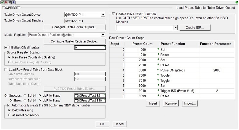
Table Driven Output Device selects which Table Driven Output this instruction will use. A Table Driven Output can only be selected for use by one Preset Table or Programmable Limit Switch at a time.
Table Driven Output Structure is the structure that is associated with this device. This structure is automatically created when the Table Driven Output itself is created.
Click the Configure Table Driven Outputs ... button to open the BRX Table Driven Outputs dialog in the System Configuration where the Table Driven Outputs are created and their High-Speed Outputs are selected.
Master Register selects the BRX High-Speed I/O channel that will provide the source count value. This can be from the on-board High-Speed I/O or from a BRX HSIO module (BX-HSIO1, BX-HSIO2, or BX-HSIO4).
High speed Ctr / Tmr 1 Accumulator selects the current count value for Counter / Timer Function 1.
High speed Ctr / Tmr 2 Accumulator selects the current count value for Counter / Timer Function 2.
High speed Ctr / Tmr 3 Accumulator selects the current count value for Counter / Timer Function 3.
Pulse Output 1 Position selects the current position value for Pulse Output 1.
Pulse Output 2 Position selects the current position value for Pulse Output 2.
Pulse Output 3 Position selects the current position value for Pulse Output 3.
Click the Configure Master Register Device ... button to open the Axis / Pulse Output Configuration dialog in the System Configuration where the High-Speed Output that contains the Master Register is configured.
The instruction's table will reset to Step 0 any time the source of the master register's count is reset, for example, if the source is a High Speed Counter, when that counter is reset the instruction's table will also be reset to Step 0. If the Master Register source is configured for rotary mode the instruction's table will reset to Step 0 if the source value wraps from the maximum rotary range value back to 0. It DOES NOT reset if the rotary source value wraps in reverse, that is it wraps from 0 to maximum rotary range value.
Initialize .InputValOffset will initialize this field in the Preset Table's associated structure to the value specified when the instruction is first enabled. This value can be changed while the Preset Table is executing. See the full discussion of this value in the section below. Note: if this option is disabled, make sure the value in this field of the Preset Table's associated structure is being initialized by some other means (ladder logic, HMI, etc.).
Use Source Register Scaling specifies whether the table entries are raw count values or values that have been scaled the same as the Master Register.
- select Raw Pulse Counts (No Scaling) to enter the Preset Count values in the Table as raw count values.
- select Use Source Register Scaling if the Master Register has been configured to scale the current count value you can use the scaled values in the table by selecting this option and entering Preset Count values that are scaled the same as the Master Register.
This instruction can source the values for the Preset table by one of two methods: load the table's values from PLC memory when the instruction is first enabled, or entering the table's values as Signed DWord constants directly in the instruction.
Enable Load Raw Preset Data from Data Block to have the instruction load the contents of the Preset Table from consecutive locations in a block of Signed DWord memory locations in the PLC - this will disable the ability to enter the values as Signed DWord constants directly in the instruction.
Table Start Address is the beginning address in PLC memory where the Preset table data is stored. This must be a Block of Signed DWords.
Number of Presets is the number of steps in the Preset table that are stored in PLC memory. A Preset Table can have up to 64 steps
Table Data Block Range will use the two values above to show the range of PLC memory that will be used as the Preset Table. When selecting this option the Data in the specified locations must be formatted properly. Improperly formatted data will generate a runtime warning message.
Each table entry consists of 2 signed DWord locations: The first DWord location is the Preset Count where the specified command will take place. This can be any value between -2,147,483,648 and 2,147,483,647. The second DWord location contains the Function Code for the command to perform and any additional data required by a command code. The upper BYTE (Byte 3) contains one of the following values to indicate the action:
If the action is Pulse ON or Pulse OFF the lower 3 bytes of the DWord location will contain the amount of time (in microseconds) the pulse will be ON or OFF respectively.
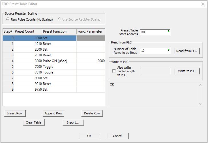
Click the PLC TDO Preset Table Editor... button to open the Preset Table Editor which allows you to edit the data values in the specified Data Block (only available when online with the PLC). The data configuration options on this dialog are the same as the main dialog.
Initial values for Table Start Address and Number of Preset Stepscome from the main instruction editor. If these values are changed while editing the table data with this dialog those values will be updated on the main instruction editor when this dialog is closed.
If the Number of Preset Steps is a variable the value in that location is read and that many of rows of data are read from the PLC to prefill the table. The Also Write Table Length to PLC selection will also be enabled and that variable location will be prefilled here so that when the table data is written back to the PLC this location will be updated as well.
This section is enabled if the Preset table's values will be entered as Signed DWord constants directly in this instruction.
Checking the Enable ISR Preset Function will allow the TDOPRESET instruction to trigger the execution of an ISR (Interrupt Service Routine) when a Preset Count is reached. Once enabled, use the drop-down selection to pick an existing ISR to run, or click the Create ISR button to create a new ISR to run. Note: this option is only available from within the TDOPRESET instruction; you cannot import the data for this function type from a numeric data block or from a CSV file.
Use OUTI / SETI / RSTI in the ISR to control other high-speed Y's, even on other BX-HSIO modules is referring to using the OUTI - Output Immediate Coil, SETI - Set Immediate Bit, and RSTI - Reset Immediate Bit instructions within the selected ISR to control additional high-speed outputs. This allows the ability to use a single PRESET value to control multiple high-speed outputs.
Preset Table contains a list of the steps in the Preset Table.
Preset Count is the pulse count value at which the action will take place. This can be any constant value between -2,147,483,648 and 2,147,483,647, or any numeric memory location.
Note: if the Preset Count is a numeric memory location - instead of a constant value - the value in that location is only read when the TDOPRESET instruction is enabled. This means any changes to the value in that memory location while the instruction is enabled will have no effect.
Preset Function selects the action to perform on the Table Driven Output.
Set turns ON the Table Driven Output.
Reset turns OFF the Table Driven Output.
Pulse On turns ON the Table Driven Output for the amount of time (in microseconds) specified in the Function Parameter which is the duration of the output pulse in microseconds (1 to 16,777,215).
Pulse Off turns OFF the Table Driven Output for the amount of time (in microseconds) specified in the Function Parameter which is the duration of the output pulse in microseconds (1 to 16,777,215).
Toggle inverts the state of the Table Driven Output: turning it ON if it is currently OFF, or OFF if it is currently ON.
Reset Count performs a reset of the Master Register which sets its current count value to the Initial Reset Value specified in the Timer / Counter Function setup, and sets the current step in the Preset Table to step 0.
Trigger ISR (Event #1-6) will cause the ISR associated with this TDOPRESET instruction to run. The Function Parameter is a value between 1 and 6 which corresponds to the .Event# field in the instruction's associated structure, which will be ON when the ISR gets executed. The .Event# fields are read-only; each time a Trigger ISR function is executed, all of the .Event# fields will be set OFF and only the .Event# field specified in the step will be set back ON.
Insert Row will insert an empty Step above the currently highlighted Step in the Table.
Append Row will add an empty Step at the end of the Table.
Delete Row will remove the currently highlighted Step from the Table.
Clear Table will remove all of the entries in the Table.
Import... will import the contents of the Preset table from a CSV file. The format of the import file is two or three numbers per line, separated by a comma or whitespace, and a maximum of 64 lines. In the example below the "//" indicates a comment, anything on that row after the "//" is ignored.:
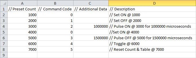
In the above example the "//" indicates a comment, anything on that row after the "//", or anything after the "//" in that cell is ignored.
Read from PLC will overwrite the contents of the table with values from PLC memory location specified in the Load Raw Preset Data from Data Block section.
Write to PLC will overwrite the contents of PLC memory at the location specified in the Load Raw Preset Data from Data Block section with the current contents of the table.
The On Success and On Error parameters specify what action to perform when this instruction completes. You do not have to use the same type of selection for both On Success and On Error.
If the Set Bit selection is used for either On Success or On Error, the specified BIT location will be SET OFF when the instruction is first enabled and will remain OFF until the instruction completes. Once complete, the appropriate Success or Error bit location ON. The specified Bit location is enabled with a SET (Latch) operation meaning that it will remain ON even if the input logic for the instruction goes OFF.
If the JMP to Stage selection is used for either On Success or On Error the target Stage must be in the same Program code-block as this instruction, you cannot specify a target Stage that exists in a different Program code-block. When the operation finishes, the target Stage will be enabled the same way as a standalone Jump to Stage (JMP) instruction would do it. The JMP to Stage option will only be available if this instruction is placed in a Program code-block.
On Success selects which of the following actions to perform if the operation is successful:
- Enable SET Bit then specify any writable bit location.
- Enable JMP to Stage then specify any
Stage number from S0 to S127 in the current Program code-block.
On Error selects which of
the following actions to perform if the operation is unsuccessful:
- Enable SET Bit then specify writable bit location.
- Enable JMP to Stage then specify any Stage number from S0 to S127 in the current Program code-block.
If either the On Success or On Error selections are set to JMP to Stage, Automatically create the SG box for any NEW stage number will be enabled which will automatically create any target stage that does not already exist.
- Below this rung will create the new target stage on a new rung following this instruction.
- At end of code-block will create the new target stage as the last rung of this Program.
Table Driven Output Structure:
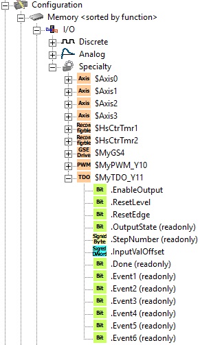
Each time a Table Driven Output is created there is an associated structure automatically created by the same name - with a prepended $. This structure will contain member fields that can be used in the Program to interact with the Table Driven Output. Each of these structures contain the following fields:
.EnableOutput: if this Bit is ON the current ON / OFF state of the Preset Table will be written to the Table Driven Output. This Bit is automatically set ON when the Preset Table is first loaded, and automatically turned OFF when the Table Driven Output is deconfigured. The ladder logic program can manually turn this Bit OFF to stop the table from writing it's state data to the Table Driven Output without having to use a TDODECFG - Deconfigure Table Driven Output to do so.
.ResetLevel: turn this Bit ON to reset the Preset Table to Step 0. Leaving the Bit ON will hold the Table in Reset until this Bit is turned OFF.
.ResetEdge: turn this Bit ON to reset the Preset Table to Step 0. This instruction will turn the Bit OFF to indicate that the table has been reset.
.OutputState (read only) is the ON / OFF state of the Output that will be written to the Table Driven Output if EnableOutput is ON.
.StepNumber (read only) is the step number from the table that is currently active. A step number of -1 indicates the Preset Table is either in Level Reset or is unconfigured.
.InputValOffset is used to adjust the current count value from the Master Register by a fixed amount before the comparison in the Step is performed.
A table that needs to start processing the Steps in the table at a particular count value, for example, a repeating pattern that needs to be started at variable distances between the pattern repetitions. In this case, InputValOffset would be set before each pass through the table.
If a table is being processed that does not expect deviations in the position value but a deviation is detected while the table is running, the difference between the expected value and the detected value (delta) can be written through this value so the table can behave as though there is no deviation seen. In this case, InputValOffset would be set any time a deviation is detected.
A table that uses fixed values to account for equipment changes, for example, encoders that have a different number of pulses per revolution. In this case, InputValOffset would be set before the first pass through the table.
Note: if the Master Register Device is configured to operate in Rotary mode, it is the user's responsibility to make sure the sum of the current Master Register value + InputValOffset stays within the device's configured Rotary Range.
Note: if the Master Register is an Axis' position, and the application is using either a servo controller or stepper controller with micro-stepping or smoothing, be aware that both of these controller types have a conversion time that will introduce some delay between the Axis' output position and the actual shaft position of the motor. The InputValOffset can be used to compensate for the conversion time by adding the number of pulses that would occur during the conversion time to the current count of the Master Register. Multiplying the servo or stepper controller's conversion time by the current velocity will yield the number of pulses that would occur during that amount of time. Using this pulse count value in the InputValOffset field will delay the comparison in the Steps by the same amount as the conversion time of the motor controller. Doing this will more closely sync the Table Driven Output's state to the actual shaft position of the motor.
.Done (read only) is ON after the last step in the TDOPRESET table has been executed, will be OFF when table is executing any of the steps.
.Event1 - .Event6 - (Read-only) are Bit locations that are set ON by the Trigger ISR Function. The .Event# fields are read-only; each time a Trigger ISR function is executed, all of the .Event# fields will be set OFF and only the .Event# field specified in the step will be set back ON.
Status Display:
The red triangle in the upper left corner of the status display indicates this is a Fully Asynchronous instruction.
The gray triangle at the right end of the input leg indicates the input is edge-triggered, meaning this instruction will execute each time the input logic transitions from OFF to ON.
OutputState / EnableOutput / Done are the current values of these numeric fields from Table Driven Output's associated structure.
See Also:
TDODECFG - Deconfigure Table Driven Output
TDOPLS - Load Programmable Limit Switch Table for Table Driven Output
TDOPRESET - Load Preset Table for Table Driven Output
Related Topics:
BRX Pulse Width Modulated Outputs
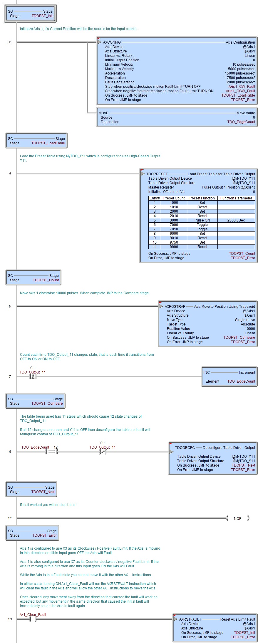
Example: