Topic: DMD0476

Module Configuration for BX-4UT4DA-3 Combination Universal Temperature Input / Universal Current / Voltage Output Module
When a Do-more CPU powers up and detects a new BX-4UT4DA-3 module it will automatically create a module configuration and assign the required I/O mapping using the first 4 available WX (32-bit signed integer) locations, the first 4 available WY (32-bit signed integer) locations, and the first 8 available X (input bit) locations required by the module.
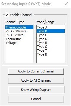
The default configuration has all of the channels disabled. Clicking the Enable *Click for Setup* button in the Module Configuration utility will open the following dialog where the default configuration can be changed. Click Enable Channel then select the type of temperature input probe or raw voltage range that will be used on this channel. Channel Type selects the type of input probe or raw voltage; Probe / Range selects the temperature range of the probe or voltage range respectively.
Once the Channel Type and Probe selection has been made, click Apply to Current Channel to use these selections for the current channel only, or Apply to All Channels to have these selections used for all of the input channels on the modules, or Cancel to exit the dialog and not retain any of the changes. The following table has all of the possible channel types and ranges:
|
Voltage |
||||
|
Type J Type K Type E Type N Type R Type S Type T Type B |
Pt10 Pt50 Pt100 Pt200 Pt500 Pt1000 Ni120 |
2.252k Ohm 3k Ohm 5K Ohm 10k Ohm 30k Ohm |
31.25 - 31.25 mVDC -31.25 - 62.5 mVDC -31.25 - 125.0 mVDC 0.0 - 1.0 VDC |
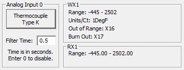
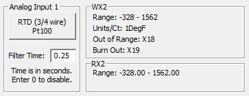
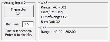
The Analog Inputs 0-3 tab set the following options that are specific to the individual channels:
Analog Input # shows the input type.
Filter time is the amount of time (in seconds) over which to apply the filter. The filter operation applies 63.2% of the difference between the current temperature reading and the last temperature value to the new temperature value over the duration of the filter time. Enabling the filter will dampen or slow down the changes in temperature to produce a more linear input value. This can be any positive value. A value of 0.0 will disable the filter.
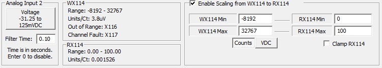
The WX# group shows the range of values, the resolution, and the units / count of the raw input value based on the current Analog Input # selection.
This group also shows the X bit memory location for the Out of Range and Burn Out indications (for the temperature selections), and the Out Of Range and Channel Fault indications (for raw voltage).
The RX# group shows the Real numeric memory location where the scaled value will be stored in the CPU, the range of potential values, and the Units / Count based on the current scale factors.
Enable Scaling from WX# to RX# (for raw voltage selection) enables the automatic scaling of the raw input value (32-bit signed integer) to engineering units (32-bit real).
WX# Min / WX# Max the minimum and maximum raw values determined by the Analog Input # selection.
Counts / (mA or VDC) displays the WX#'s Min and Max values in terms of counts or milliamps / volts depending on the Analog Input selection type.
RX# Min / RX# Max contains the minimum and maximum values for the engineering units.
Clamp RX# (if enabled) and the calculated scaled value is lower than RX # Min or higher than RX# Max, the specified Min and Max values will be used.
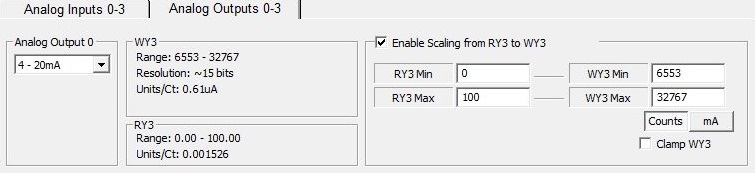
The Analog Outputs 0-3 tab sets the following options that are specific to the individual channels:
Analog Output # (voltage) 0 - 5V, 0 - 10V, +/- 5V, +/- 10V, (current) 4 - 20mA or +/- 20mA.
The WY# shows the range of values, the resolution, and the units / count of the raw output based on the current Analog Output # selection. The range for bipolar voltage and current selections is -32768 to +32767; the range for unipolar voltage selections is 0 - 32767; the range for the unipolar current selection is 6553 - 32767.
The RY# group (if automatic scaling is enabled for this channel) shows the Real numeric memory location where the engineering unit value is stored in the CPU, the range of potential values and the Units / Count based on the current scale factors.
Enable Scaling from RY# to WY# enables the automatic scaling of the engineering units (32-bit real) to raw output value (32-bit signed integer).
RY# Min / RY# Max contains the minimum and maximum values for the engineering units.
WY# Min / WY# Max the minimum and maximum raw values determined by the Analog Output # selection.
Counts / (mA or VDC) displays the WX#'s Min and Max values in terms of counts or milliamps / volts depending on the Analog Output selection type.
Clamp WY# (if enabled) and the calculated scaled value is lower than WY # Min or higher than WY# Max, the specified Min and Max values will be used.
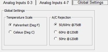
The Global Settings tab has settings that affect all of the channels on the module.
Temperature Scale selects whether the reported values for all of the channels will be in Degrees Fahrenheit or Degrees Celsius.
A/C Rejection selects the level of A/C noise rejection the A/D conversion will apply. The default value is for either 50 or 60 Hz @75dB powered systems. Select 60Hz @ 120dB for 60Hz powered systems or 50Hz @ 120dB for 50Hz powered systems for additional noise filtering.
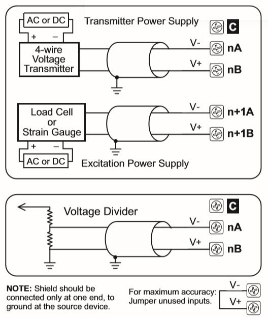
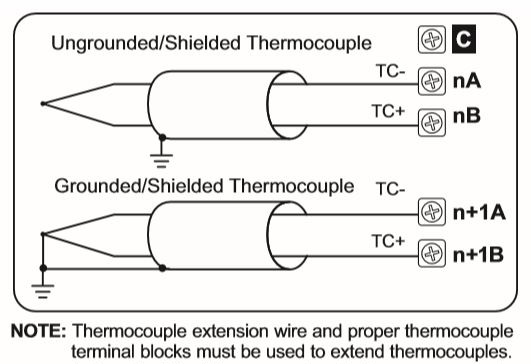
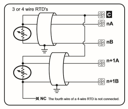
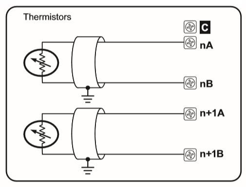
Input Channel Wiring Diagrams:
Channel is configured as a Thermocouple:
Channel is configured as 3-wire RTD or 4-wire RTD:
Channel is configured as 2-wire RTD:

Channel is configured as Thermistor:
Channel is configured as Voltage: