Topic: DMD0396

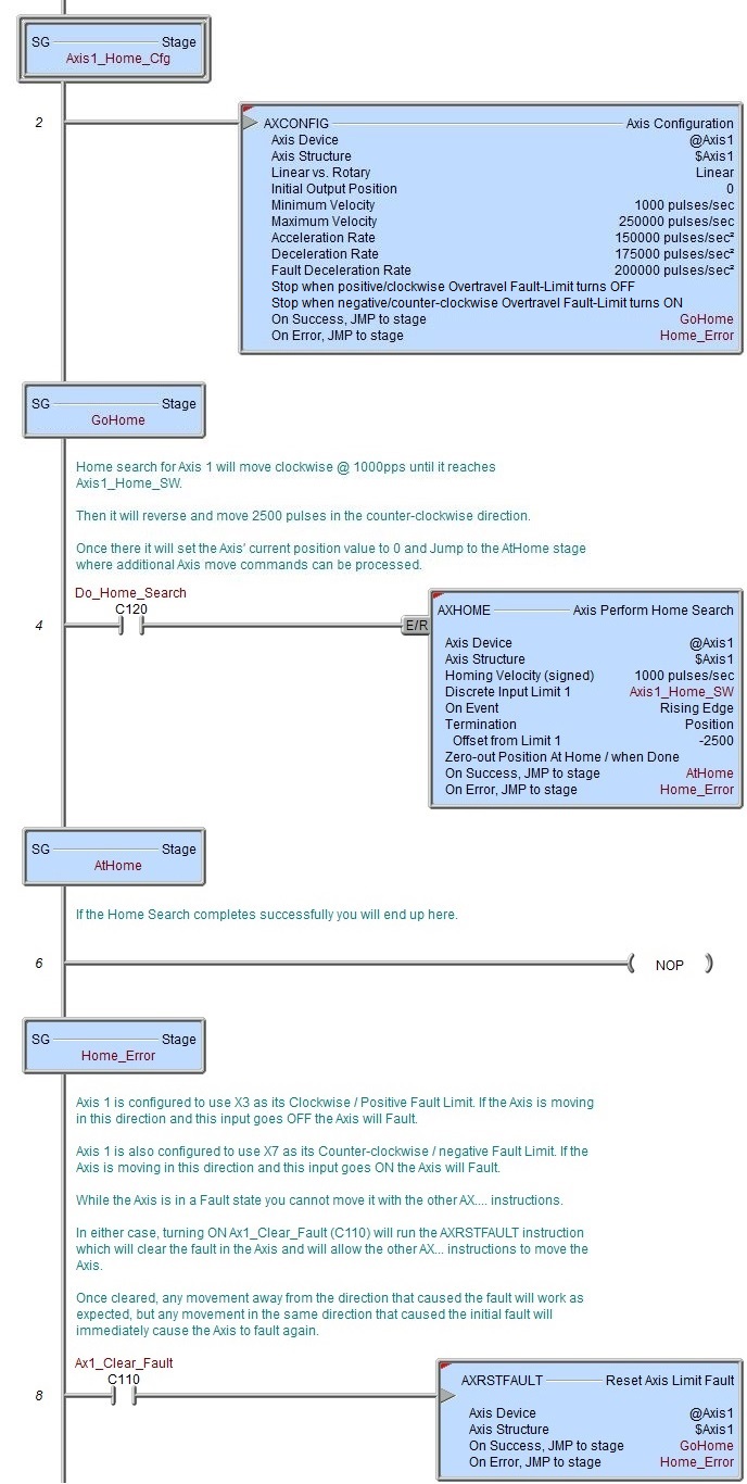
AXHOME - Axis Perform Home Search
Note: this instruction can only be used with a BRX CPU !
The Axis Perform Home Search (AXHOME) instruction is used to perform a sequence of steps needed to move an Axis to a known starting position.
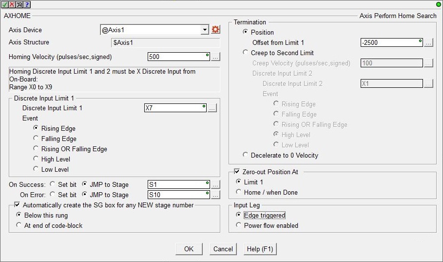
Axis Device selects which Axis this instruction will use - remember that Axis 0 is a virtual Axis meaning it will not generate pulses to physical outputs on the PLC.
Axis Structure displays the name of structure associated with this Axis. This structure was automatically created when the Axis itself was created.
Click the gear symbol at the right end of the Axis Device to open the BRX Axis / Pulse Outputs configuration dialog where the Axis' Pulse Output Mode is set and its High-Speed I/O outputs are selected.
Homing Velocity (Signed) is the maximum velocity the Axis will ramp up to when moving toward Discrete Input Limit 1. The Axis will ramp up and down using the Axis' current Acceleration and Deceleration settings. This can be any constant value between -2,000,000 and 2,000,000 or any numeric location containing a value in that range. The sign of the value will indicate the direction of travel: positive numbers will move the Axis clockwise, negative numbers will move the Axis counter-clockwise. Note: only the BX-HSIO4 module can operate at velocities above 250KHz; attempting to use a velocity above 250KHz for an Axis that is using the on-board High-Speed I/O, or an Axis on a BX-HSIO1 or BX-HSIO2 module will result in a maximum velocity of that Axis still being 250KHz.
Discrete Input Limit 1 : the Home Search operation requires at least one discrete input.
Discrete Input is the discrete input where the Home limit switch is connected. Note: the Limit must use a discrete input on the same hardware as the outputs used by the Axis, this means if the Axis is using the on-board discrete outputs, the Limit must use one of the on-board discrete inputs; if the Axis is using the discrete outputs on one of the BRX HSIO modules (BX-HSIO1, BX-HSIO2, or BX-HSIO4) the Limit must use one of the discrete inputs on the same HSIO module.
Event selects which of the following conditions will indicate the Home switch has been reached: Rising Edge / Falling Edge / Rising OR Falling Edge / High Level / Low Level.
Termination specifies what action to take after reaching the Home switch (Input Limit 1):
- Position will use the Axis' current positioning configuration to move the Axis to a position relative to the position of Discrete Input Limit 1. If the Axis is configured for Position Based on Encoder this value is the encoder count multiplied by the Axis' Pulse Output / Encoder Scale Factor. If the Axis is configured for Position Based on Pulse Output, this value is the number of output pulses.
Offset from Discrete Input Limit 1 means that when Discrete Input Limit 1 is reached the Axis marks the location of the switch and will then move the Axis toward the specified Position value.
If the specified Position is in the same direction the Axis was already moving, the Axis will continue moving that direction then decelerate to the specified Position value.If the specified Position is in the opposite direction the Axis was moving, the Axis will decelerate to 0, reverse direction back to the point where the switch Home switch was located, then move to the Position value.
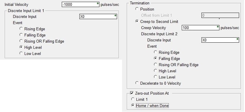
- Creep to Second Limit will move the Axis to a second discrete Input Limit switch.
Creep Velocity (Signed) is the maximum frequency the Axis will ramp up to when moving toward Discrete Input Limit 2. The Axis will ramp up and down using the Axis' current Acceleration and Deceleration settings. This can be any constant value between -2,000,000 and 2,000,000 or any numeric location containing a value in that range. The sign of the value will indicate the direction of travel: positive numbers will move the Axis clockwise, negative numbers will move the Axis counter-clockwise. An immediate stop occurs after Limit 2 is reached.
Discrete Input Limit 2 will use a discrete input for Limit 2. This could be a second discrete input or the same input as Discrete Input Limit 1. Note: the Limit must use a discrete input on the same hardware as the outputs used by the Axis, this means if the Axis is using the on-board discrete outputs, the Limit must use one of the on-board discrete inputs; if the Axis is using the discrete outputs on one of the BRX HSIO modules (BX-HSIO1, BX-HSIO2, or BX-HSIO4) the Limit must use one of the discrete inputs on the same HSIO module.
Discrete Input is the discrete input where the Discrete Input Limit 2 switch is connected. This must be one of the on-board discrete inputs.
Event selects which of the following conditions will indicate Discrete Input Limit 2 has been reached: Rising Edge / Falling Edge / Rising OR Falling Edge / High Level / Low Level.
- Decelerate to 0 Velocity means the Axis will decelerate from the Homing Velocity to 0.
Enable the Zero Position At option to have the Axis set it's Current Position to 0 after the following step of the Home Search operation:
- Discrete Input Limit 1 will set the Current Position to 0 when the Discrete Input Limit 1 switch is reached. Any additional movement of the Axis during the Termination phase will be reflected in the Axis Current Position value.
- Home / When Done will set the Current Position to 0 when all phases of the Home Search operation is complete.
There are examples of the movement paths for some of the most popular Home Search configurations available at the bottom of the page.
Input Leg specifies how the instruction will be enabled to run:
- Edge Triggered means each time the input logic transition from OFF to ON this instruction will run to completion. This selection does not allow the Home Search operation to be interrupted once it has started except by manually turning OFF the MasterEnable for the Axis, which will put the Axis into a Fault condition that must be cleared before the Axis will be permitted to move. Use the AXRSTFAULT - Reset Axis Limit Fault instruction to clear an Axis Fault.
- Power Flow Enabled means when the input logic transition from OFF to ON the instruction will begin to execute, and will continue executing as long as the input logic remains ON. This selection allows the Home Search operation to be interrupted by turning the input logic OFF; this is an error condition but the it does not put the Axis into a Fault condition.
The On Success and On Error parameters specify what action to perform when this instruction completes. You do not have to use the same type of selection for both On Success and On Error.
If the Set Bit selection is used for either On Success or On Error, the specified BIT location will be SET OFF when the instruction is first enabled and will remain OFF until the instruction completes. Once complete, the appropriate Success or Error bit location will be set ON. The specified Bit location is enabled with a SET (Latch) operation (not an OUT operation) meaning that it will remain ON even if this instruction's input logic goes OFF.
If the JMP to Stage selection is used for either On Success or On Error the target Stage must be in the same Program code-block as this instruction, you cannot specify a target Stage that exists in a different Program code-block. When the operation finishes, the target Stage will be enabled the same way as a standalone Jump to Stage (JMP) instruction would do it. The JMP to Stage option will only be selectable if this instruction is placed in a Program code-block.
On Success selects which of the following actions to perform if the operation is successful:
- Enable Set Bit then specify any writable bit location.
- Enable JMP to Stage then specify
any Stage number from S0 to S127 in the current Program code-block.
On Error selects which of
the following actions to perform if the operation is unsuccessful:
- Enable SET Bit then specify writable bit location.
- Enable JMP
to Stage then specify any Stage number
from S0 to S127 in the current Program code-block.
If either the On Success or On Error selections are set to JMP to Stage, Automatically create the SG box for any NEW stage number will be enabled which will automatically create any target stage that does not already exist.
- Below this rung will create the new target stage on a new rung following this instruction.
- At end of code-block will create the new target stage on the last rung of this Program.
Status Display
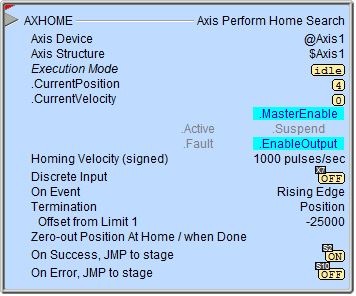
If the instruction is configured as Edge Triggered, the red triangle in the upper left corner of the status display indicates this is a Fully Asynchronous instruction.
Execution Mode shows the current mode of the Axis (see a list of the possible execution mode values).
Execution Mode / CurrentPosition / CurrentVelocity are the current values of these numeric fields from Axis' associated structure.
MasterEnable / Active / Suspend / Fault / EnableOutput are the current state of these Bit values from that Axis' associated structure.
A detailed description of the Numeric and Bit fields in the Axis structure is available in AXCONFIG - Axis Configuration.
See Also
AXSETPROP - Axis Set Properties
AXRSTFAULT - Reset Axis Limit Fault
AXSCRIPT - Run a Sequence of Axis Commands
AXHOME - Axis Perform Home Search
AXPOSTRAP - Axis Move to Position Using Trapezoid
AXPOSSCRV - Axis Move to Position Using S-Curve
AXVEL - Axis Set Velocity Mode
AXGEAR - Axis Electronic Gearing
AXFOLLOW - Axis Position Following with Offset
AXCAM - Axis Electronic Camming
Related Topics
Example
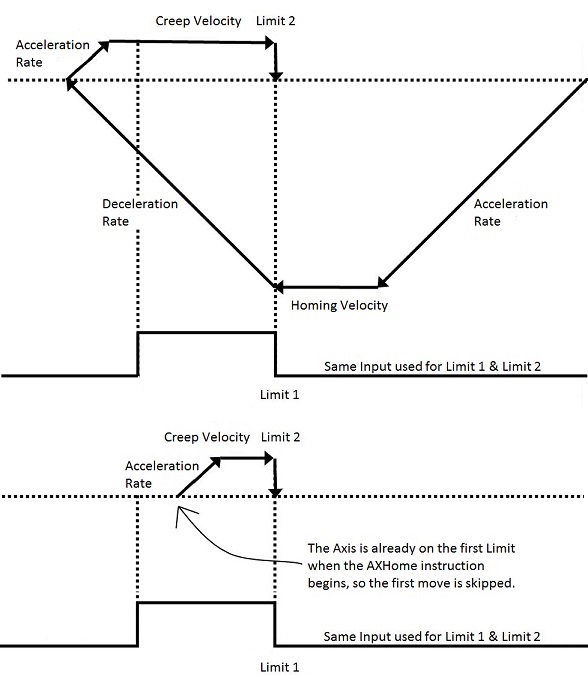
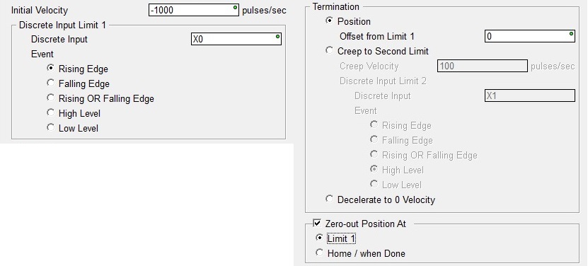
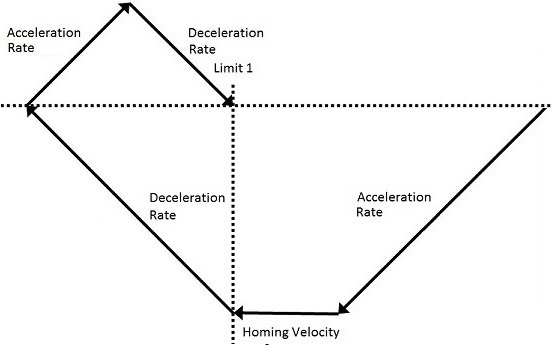
Movement paths for some of the more popular Home Search configurations.
Termination at Position of Limit 1 - Axis moves back to Limit 1 after decelerating to 0 - Axis Position is set to Zero at Limit 1.
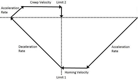
Termination using Creep to Second Limit - Axis decelerates to 0 after Limit 1 then creeps to Limit 2 and immediately stops.
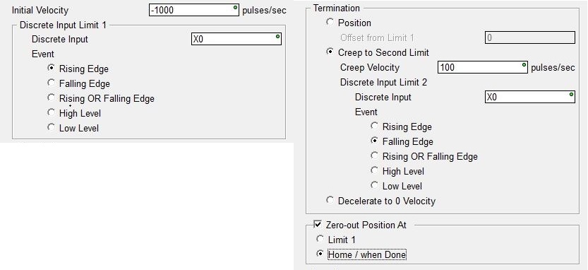
Termination using Creep to Second Limit - Axis creeps to Limit 2 then immediately stops - Limit 1 uses Level so if already at Limit 1 the first move is skipped.