Topic: DMD0394

AXCONFIG - Axis Configuration
Note: this instruction can only be used with a BRX CPU !
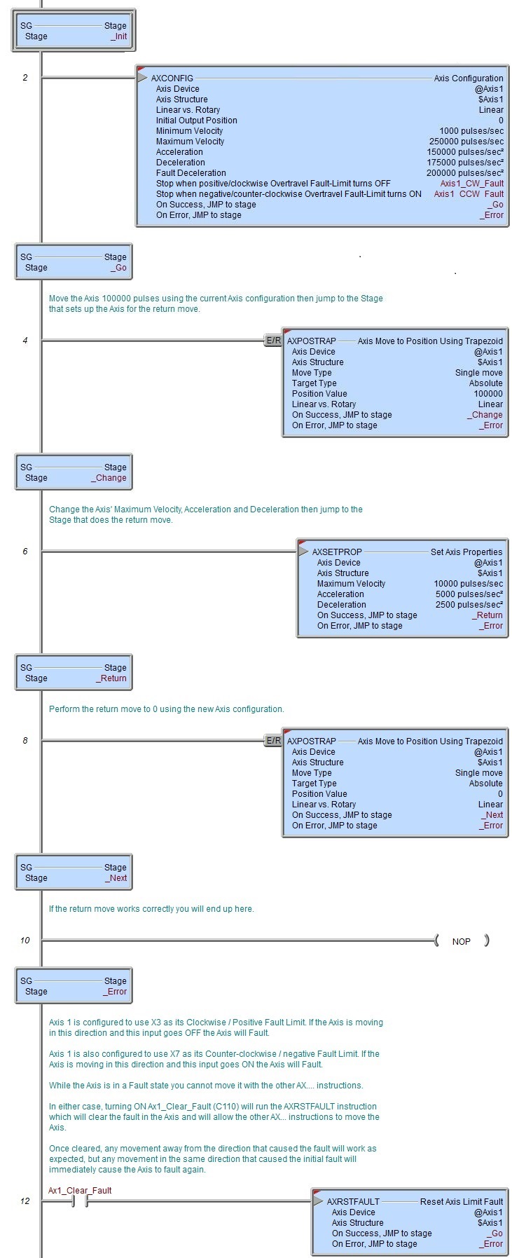
The Axis Configuration (AXCONFIG) instruction is used to configure the runtime parameters for an Axis using the on-board high-speed I/O or one of the HSIO modules (BX-HSIO1, BX-HSIO2, or BX-HSIO4). There are no default values for an Axis, meaning that an Axis must be configured by an AXCONFIG instruction before it can be used by any of the other Axis instructions.
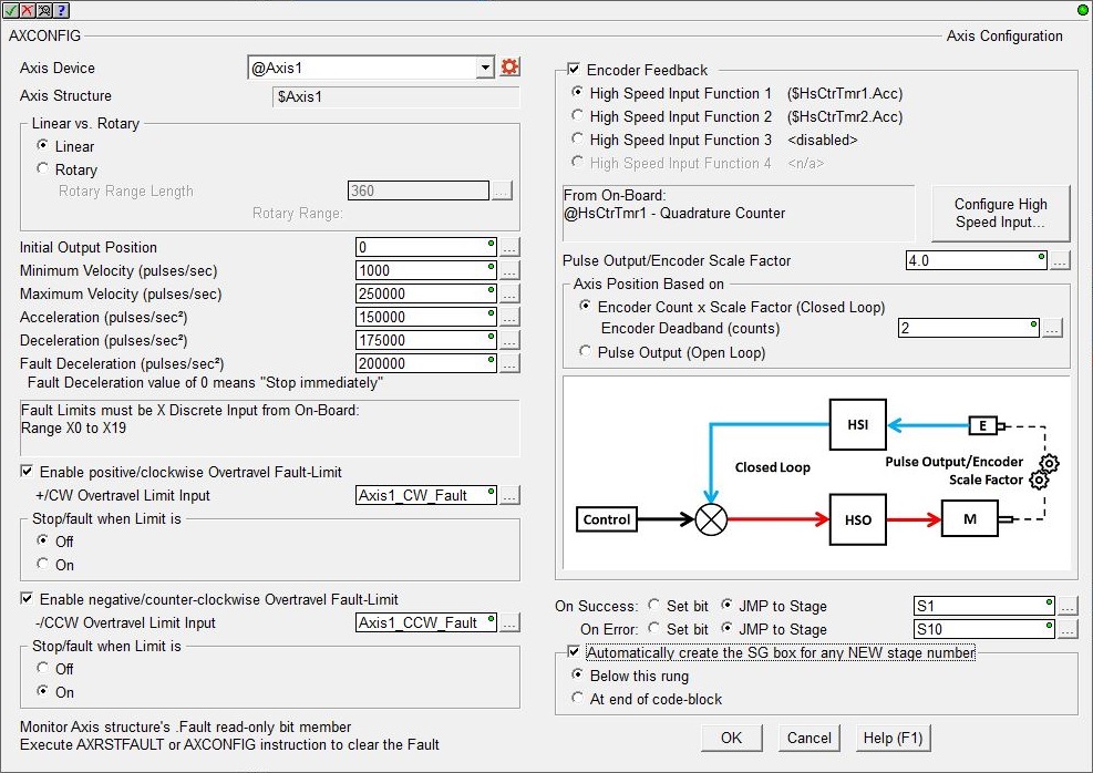
Axis Device selects which Axis this instruction will use - remember that Axis 0 is a virtual Axis meaning it will not generate pulses to physical outputs on the PLC.
Axis Structure displays the name of structure associated with this Axis. This structure was automatically created when the Axis itself was created.
Click the gear symbol at the right end of the Axis Device to open the BRX Axis / Pulse Outputs configuration dialog where the Axis' Pulse Output Mode is set and its High-Speed I/O outputs are selected.
Linear vs. Rotary selects the type of movement that the output pulses will generate.
Linear actuators move forward or backwards on a fixed linear path. The movement of linear actuators are defined in linear units such as inches or millimeters. Since linear actuators only move in two directions on a fixed path, linear actuators are defined as finite meaning they have a set distance that they can travel in either direction before they must stop.
Rotary actuators produce rotary motion, meaning that the actuator revolves on a circular path. Movement from this type of actuator is defined in rotary units, typically degrees. A rotary table doesn’t have a fixed distance it can travel; it can keep spinning in the same direction for as long as necessary. The count for a rotary input is kept within a defined range. When the input goes beyond one end of this range, the count wraps to the other end of the range.
Rotary Range Length is the range of count values for one complete rotation. This can be any positive constant value or any numeric location with a value in that range.
Rotary Range displays the range of count values based on the Rotary Range Length value entered above. The Rotary Range is 0-based so it begins at 0 and extends to 1 less than the Length, then wraps back to 0. For example, a Rotary Range Length of 360 would have a Rotary Range of 0 to 359. When the position value gets to 359, the next clockwise movement wraps the position value back to 0. Similarly, when the position value is 0 the next counter-clockwise movement wraps the position value to 359.
Initial Output Position is the position the Axis will be set to when the Axis is first enabled. This can be any constant value or any numeric location.
Minimum Velocity is the slowest frequency (pulses / sec) of output pulses that will be generated while the output is enabled. Be aware this value may be internally adjusted up by the Axis if the Acceleration is set to a sufficiently high number. This can be any positive constant from 10 to 2,000,000, or any numeric location containing a value in that range.
Maximum Velocity is the fastest frequency (pulses / sec) of output pulses that will be generated while the output is enabled. This can be any positive constant from 10 to 2,000,000, or any numeric location containing a value in that range.
Acceleration is the rate (pulses / sec2 ) at which the velocity will change when the Axis is ramping up from a slower pulse rate to a higher pulse rate, effectively it is how quickly the Axis will move from the current velocity to the maximum velocity; the larger the value, the more quickly the Axis will accelerate. This can be any positive constant greater than 0 or any numeric location containing a value in that range.
Deceleration is the rate (pulses / sec2 ) at which the velocity will change when the Axis is ramping down from a faster pulse rate to a slower pulse rate, effectively it is how quickly the Axis will move from the current velocity to the minimum velocity; the larger the value, the more quickly the Axis will accelerate. This can be any positive constant greater than 0 or any numeric location containing a value in that range.
Fault Deceleration is used any time a Fault Limit is reached or the Axis' .MasterEnable is manually turned OFF, the Axis will decelerate to 0 Hz at this specified rate (pulses / sec2 ). A value of 0 will cause the Axis to immediately stop moving. This can be any positive constant or any numeric location containing a value in that range.
Enable Positive / Clockwise Over-travel Fault-Limit will optionally enable the use of a limit switch that will cause the Axis to Fault (Stop) if the Axis tries to move past the fault limit in a clockwise (CW) direction. Note: the Fault Limits must use discrete inputs on the same hardware as the outputs used by the Axis, this means if the Axis is using the on-board discrete outputs, the Fault Limits must use the on-board discrete inputs; if the Axis is using the discrete outputs on one of the BRX HSIO modules (BX-HSIO1, BX-HSIO2, or BX-HSIO4) the Fault Limits must use discrete inputs on the same HSIO module.
Limit Input specifies where the Positive Fault Limit switch is connected.
Stop When Limit is specifies which state of the Limit Input will generate the fault condition:
- OFF means a fault is generated when the Input is OFF.
- ON (default) means a fault is generated when the Input is ON.
Enable Negative / Counter-Clockwise Over-travel Fault-Limit will optionally enable the use of a limit switch that will cause the Axis to Fault (Stop) if the Axis tries to move past the fault limit in a counter-clockwise (CCW) direction.
Limit Input specifies where the Negative Fault Limit switch is connected.
Stop When Limit is specifies which state of the Limit Input will generate the fault condition:
- OFF means a fault is generated when the Input is OFF.
- ON (default) means a fault is generated when the Input is ON.
Note: use an Axis Reset Fault (AXRSTFLT) or re-run the Axis Configuration (AXCONFIG) instruction to clear the fault in the Axis. Any attempt to move the Axis in the same direction that caused the fault will immediately generate another fault condition. Movement of the Axis in the opposite direction is permitted.
The section below will contain a graphic that will be relevant to the configuration.
Enable the Encoder Feedback option if an incremental encoder is being used to provide the feedback. Select one of the following to specify which of the High-Speed Inputs the encoder is connected to:
High Speed Input Function 1 / High Speed Input Function 2 / High Speed Input Function 3 / High Speed Input Function 4 Note: the encoder feedback must come from one of the High-Speed Counters on the same hardware as the Axis outputs, meaning, if the Axis is using on-board discrete outputs then the Encoder must be using on-board discrete inputs; if the Axis is using discrete outputs on one of the BRX HSIO modules (BX-HSIO1, BX-HSIO2, or BX-HSIO4) then the Encoder must be use discrete inputs on the same HSIO module.
Click Configure High-Speed Input to change the configuration of the currently selected High-Speed Input; its current configuration and the name of the associated structure are displayed in the box on the left.
Pulse Output / Encoder Scale Factor is the value required to bring the motor position value and the encoder value into alignment if they have different pulses-per-revolution values.
Axis Position Based on selects the source of the Axis' .CurrentPosition value:
- Encoder Count x Scale Factor (Closed Loop) means the value is generated from the encoder's current count value multiplied by the Pulse Output / Encoder Scale Factor.
Having an Encoder Deadband (counts) around the encoder current position can prevent the pulse output from generating alternating small pulses trying to get the input value to an exact number. This value is applied both above and below the encoder value, for example, a value of 2 will be a deadband of 2 above and two below for a span of 4 counts. This is only available when the Position is Based on Encoder, and becomes critically important as the Pulse Output / Encoder Scale Factor value approaches 1.
- Pulse Output (Open Loop) means the value is the number of generated output pulses.
Note: when Encoder Feedback is enabled for an Axis, the Axis' associated structure member .FollowingError will contain the difference between the output pulse count and the encoder's input value. An increasing .FollowingError value while the Axis is moving indicates that either the motor has stalled or there is mechanical slippage between the motor and the encoder.
The On Success and On Error parameters specify what action to perform when this instruction completes. You do not have to use the same type of selection for both On Success and On Error.
If the Set Bit selection is used for either On Success or On Error, the specified BIT location will be SET OFF when the instruction is first enabled and will remain OFF until the instruction completes. Once complete, the appropriate Success or Error bit location will be set ON. The specified Bit location is enabled with a SET (Latch) operation (not an OUT operation) meaning that it will remain ON even if this instruction's input logic goes OFF.
If the JMP to Stage selection is used for either On Success or On Error the target Stage must be in the same Program code-block as this instruction, you cannot specify a target Stage that exists in a different Program code-block. When the operation finishes, the target Stage will be enabled the same way as a standalone Jump to Stage (JMP) instruction would do it. The JMP to Stage option will only be selectable if this instruction is placed in a Program code-block.
On Success selects which of the following actions to perform if the operation is successful:
- Enable Set Bit then specify any writable bit location.
- Enable JMP to Stage then specify
any Stage number from S0 to S127 in the current Program code-block.
On Error selects which of
the following actions to perform if the operation is unsuccessful:
- Enable SET Bit then specify writable bit location.
- Enable JMP
to Stage then specify any Stage number
from S0 to S127 in the current Program code-block.
If either the On Success or On Error selections are set to JMP to Stage, Automatically create the SG box for any NEW stage number will be enabled which will automatically create any target stage that does not already exist.
- Below this rung will create the new target stage on a new rung following this instruction.
- At end of code-block will create the new target stage on the last rung of this Program.
Axis Structure Members
|
Structure Member |
Writable |
||
|
32-bit Signed |
yes |
The velocity (pulses per second) the Axis is ramping toward.
|
|
|
CurRateOfChg
|
32-bit Signed |
yes |
The current velocity (pulses per second) the Axis is using during the ramp.
|
|
32-bit Signed |
no |
The pulse count the Axis is moving toward.
|
|
|
32-bit Signed |
no |
The velocity (pulses per second) the Axis is currently using.
|
|
|
CurrentPosition |
32-bit Signed |
no |
The pulse count where the Axis is currently located.
|
|
FollowingError |
32-bit Signed |
no |
When an Axis is configured to use encoder feedback as the Axis position, this value is the difference between the output pulse count (TargetPosition) and the encoder input value (Current Position). This value is always reported in pulse counts, not in encoder count values.
An increasing value could indicate a mechanical problem where either the motor has stalled or there is mechanical slippage between the motor and the encoder. It could also indicate a mathematical problem where the Filter Time Constant is too large or the resolution of the encoder is too small.
|
|
32-bit Signed |
no |
When an Axis is a Slave Axis in an AXGEAR - Axis Electronic Gearing, a Follower in an AXFOLLOW - Axis Position Following with Offset mode, or a slave in an AXCAM - Axis Electronic Camming mode, this member field will contain the difference between the position of the Master Axis and the projected location of the Slave Axis.
This value is always reported in pulse counts, not in encoder count values.
A negative value indicates the Slave Axis is running behind the Master Axis; a positive value indicates the Slave Axis running ahead of the Master Axis.
|
|
|
Bit |
yes |
When this bit transitions from OFF to ON the Axis will decelerate to a stop using the Axis' Deceleration.
When this bit transitions from ON to OFF the Axis will resume the current motion instruction, accelerating back to TargetVelocity.
|
|
|
MasterEnable |
Bit |
yes |
This Bit location is automatically set ON when the Axis is properly configured.
If the bit transitions from ON to OFF the Axis will decelerate to a stop using the Axis' Fault Deceleration Rate. This is considered a Fault condition so either a Reset Axis Limit Fault (AXRSTFAULT) or an AXCONFIG - Axis Configuration instruction must be executed to clear the Fault in the Axis before the Axis will operate again.
|
|
EnableOutput |
Bit |
yes |
This Bit location is automatically set ON when the Axis is properly configured.
If the bit transitions from ON to OFF the Axis will immediately stop sending output pulses to the High-Speed Output - if the Axis is moving is WILL NOT decelerate. This is not considered an Error or Fault condition so all other aspects of the Axis will continue to operate normally.
|
|
Configured |
Bit |
no |
This Bit location will be ON if an AXCONFIG - Axis Configuration has successfully been executed.
|
|
Active |
Bit |
no |
This Bit location will be ON any time the Axis is enabled and in any Mode other than idle. In this mode the Axis will move if instructed to do so.
|
|
Bit |
no |
This Bit location will be ON when TargetVelocity = CurrentVelocity.
|
|
|
Bit |
no |
This Bit location will be ON when TargetPosition = CurrentPosition.
|
|
|
ScriptBusy |
Bit |
no |
This Bit location will be ON when the Axis is currently being controlled by an AXSCRIPT instruction.
|
|
Fault |
Bit |
no |
Will be ON when either Fault Limit for an Axis is ON, or when the Axis' MasterEnable has been manually turned OFF. A Reset Axis Limit Fault (AXRSTFAULT) or an AXCONFIG - Axis Configuration instruction must be executed to clear the Fault in the Axis before the Axis will operate again.
|
|
8-bit Unsigned |
no |
The current execution mode of the Axis. The following values are valid:
00 (Unconfigured) - the Axis has not been configured with a AXCONFIG instruction.
01 (Idle) - the Axis is not moving.
65 (Positive Limit Fault) - the Fault Limit in the positive / clockwise has been reached.
66 (Negative Limit Fault) - the Fault Limit in the negative / counter-clockwise has been reached.
67 (Fault Both Limits) - the same input was specified as the Positive and Negative Fault Limit and it has been reached.
68 (Fault Master Enable) - the Axis' MasterEnable has been manually turned OFF.
69 (Fault-SCurve) - in an AXSCRIPT - Run a Sequence of Axis Commands instruction, an attempt was made to run a Move to Absolute Position w/ S-Curve or a move to Relative Position w/ S-Curve at a point when the Axis was accelerating or decelerating (the Axis' .RateOfOChange is non-zero), or the target position is in the opposite direction the Axis is moving, or the Axis is at a velocity that would not allow the axis to get to the target position without over-shooting.
128 (Velocity) - the Axis is running an AXVEL - Axis Set Velocity Mode instruction that does not ramp to the Target Velocity.
129 (Smart Velocity) - the Axis is running an AXVEL - Axis Set Velocity Mode or AXJOG - Axis Jog Mode instruction that ramps to a specified Target Velocity.
130 (Smart Position) - the Axis is running an AXPOSTRAP - Axis Move to Position instruction.
131 (Electronic Gearing) - the Axis is running an AXGEAR - Axis Electronic Gearing instruction.
132 (Follower) - the Axis is running an AXFOLLOW - Axis Position Following with Offset instruction.
133 (Cam) - the Axis is running an AXCAM - Axis Electronic Camming instruction.
134 (Terminate) - a fault limit has been reached or the MasterEnable has been manually turned OFF while making a trapezoid move, so the Axis is stopping, either immediately or decelerating to 0 using a trapezoid profile.
135 (S-Curve Velocity) - the Axis is running an AXVEL - Axis Set Velocity Mode instruction that ramps to a specified Target Velocity using an S-Curve path.
136 (S-Curve-Terminate) - a fault limit has been reached or the MasterEnable has been manually turned OFF while making an S-curve move, so the Axis is stopping by decelerating to 0 using an S-Curve path.
|
|
|
.ScriptStep |
Signed Byte |
no |
If an AXSCRIPT - Run a Sequence of Axis Commands instruction is running, this will show the step in that instruction that is currently being executed. This value is set to 1 when the AXSCRIPT instruction is enabled. If the instruction is disabled or the Axis itself has a fault before all steps are completed, this value will remain indicating which step was active when the instruction stopped executing.
|
|
Signed DWord |
yes |
If an AXSCRIPT - Run a Sequence of Axis Commands instruction is running, and the current step is executing a Start Timer command, this will show the amount of time (in milliseconds) remaining before that Timer expires.
|
|
|
.Counter |
Signed DWord |
yes |
If an AXSCRIPT - Run a Sequence of Axis Commands instruction is running, and the current step is a For / Next Loop, this location contains the current loop count as it counts down
|
Status Display
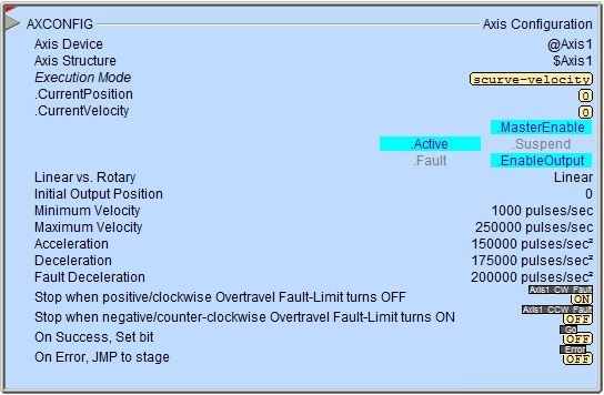
The red triangle in the upper left corner of the status display indicates this is a Fully Asynchronous instruction.
Execution Mode / CurrentPosition / CurrentVelocity are the current values of these numeric fields from Axis' associated structure.
MasterEnable / Active / Suspend / Fault / EnableOutput are the current state of these Bit values from that Axis' associated structure.
See Also
AXSETPROP - Axis Set Properties
AXRSTFAULT - Reset Axis Limit Fault
AXSCRIPT - Run a Sequence of Axis Commands
AXHOME - Axis Perform Home Search
AXPOSTRAP - Axis Move to Position Using Trapezoid
AXPOSSCRV - Axis Move to Position Using S-Curve
AXVEL - Axis Set Velocity Mode
AXGEAR - Axis Electronic Gearing
AXFOLLOW - Axis Position Following with Offset
AXCAM - Axis Electronic Camming
Related Topics
Example