Topic: DMD0461

PWMOUT - Pulse Width Modulated Output
Note: this instruction can only be used with a BRX CPU !
The Pulse Width Modulated Output (PWMOUT) instruction is used to control one of the Pulse Width Modulated outputs on a BRX PLC by manipulating the values in the PWM Output's associated structure. Refer to the help section on BRX Pulse Width Modulated Outputs for a full discussion on how PWM outputs work, and how they are configured in a BRX PLC.
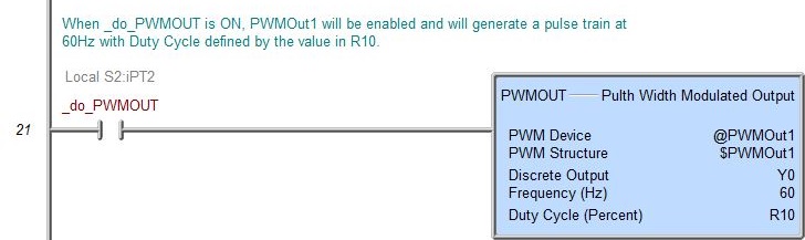
When the input logic is ON the instruction will generate pulses, when the input logic is OFF no pulses are generated.
Parameters:
Note: Use the F9 key or click the 'three dot box' at the right edge of the parameter field to open the Default Element Selection Tool (the Element Picker or the Element Browser) or use the Down-Arrow key (Auto-Complete) on any parameter field to see a complete list of the memory locations that are valid for that parameter of the instruction.
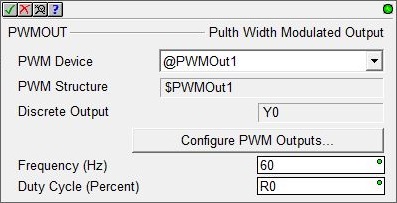
PWM Device selects which PWM Output to control.
PWM Structure shows the name of the PWM Output's associated structure.
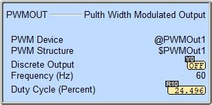
Discrete Output shows the Discrete Output the PWM Device is configured to use.
Click the Configure PWM Outputs... button to configure an existing PWM Output Device or to create a new one.
Frequency (Hz) is the carrier frequency the PWM Output will generate. This can be any constant from 0 to 65535.
Duty Cycle (Percent) is the percentage of one pulse where the output is ON, during the remaining portion the output will be OFF. This can be any numeric location containing a value between 0.0 and 100.0. The value in this location can be changed while the instruction is enabled.
Status Display:
See Also:
TDOPLS - Load Programmable Limit Switch Table for Table Driven Output
TDOPreset - Load Preset Table for Table Driven Output
FLASHER - Cycle Output On / Off
Related Topics:
BRX Pulse Width Modulated Outputs
Example: