Topic: DMD0400

AXSETPROP - Axis Set Properties
Note: this instruction can only be used with a BRX CPU !
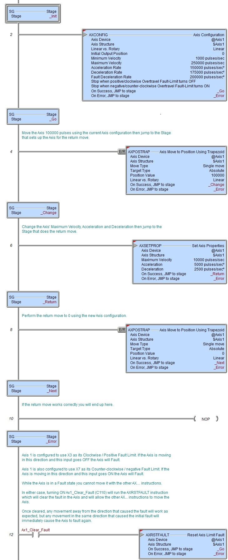
The Set Axis Properties (AXSETPROP) instruction is used to make changes to some of the configured parameters of an Axis without having to re-run an Axis Configuration (AXCONFIG) instruction to do so. Changes made to the Axis by this instruction will be reflected in all subsequent instructions that reference this Axis, they will not affect any Axis instructions that are currently running.
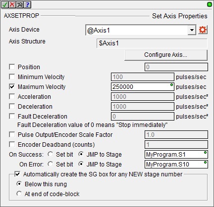
Axis Device selects which Axis this instruction will use - remember that Axis 0 is a virtual Axis meaning it will not generate pulses to physical outputs on the PLC.
Axis Structure displays the name of structure associated with this Axis. This structure was automatically created when the Axis itself was created.
Click the gear symbol at the right end of the Axis Device to open the BRX Axis / Pulse Outputs configuration dialog where the Axis' Pulse Output Mode is set and its High-Speed I/O outputs are selected.
Position is the Current Position of the Axis. This can be any constant value or any numeric location.
Minimum Velocity (pulses / second) - the slowest frequency of output pulses that will be generated when the output is enabled. This can be any positive constant from 10 to 2,000,000, or any numeric location with a value in that range.
Maximum Velocity is the fastest frequency (pulses / second) of output pulses that will be generated when the output is enabled. This can be any positive constant from 10 to 2,000,000, or any numeric location with a value in that range. Note: only the BX-HSIO4 module can operate at velocities above 250KHz; attempting to use a velocity above 250KHz for an Axis that is using the on-board High-Speed I/O, or an Axis on a BX-HSIO1 or BX-HSIO2 module will result in a maximum velocity of that Axis still being 250KHz.
Acceleration) is the rate (pulses / second2at which the velocity will change when the Axis is ramping up from a slower pulse rate to a higher pulse rate, effectively it is how quickly to move from the current velocity to the maximum velocity. This can be any positive constant greater than 0 or any numeric location with a value in that range.
Deceleration) is the rate (pulses / second2 at which the velocity will change when the Axis is ramping down from a faster pulse rate to a slower pulse rate, effectively it is how quickly to move from the current velocity to the minimum velocity. This can be any positive constant greater than 0 or any numeric location with a value in that range.
Fault Deceleration is the rate (pulses / second2) at which the Axis will decelerate to a velocity of 0 any time a Fault Limit is reached or the Axis' MasterEnable is manually turned OFF. A value of 0 will cause the Axis to immediately stop moving. This can be any positive constant value or any numeric location with a value in that range.
Pulse Output / Encoder Scale Factor is the scale value required to bring the motor and the encoder feedback into alignment if the output pulse count and the encoder have different pulse-per-revolution values.
Having an Encoder Deadband (counts) value around the encoder current position can prevent the Axis from generating alternating small output pulses trying to get the input value to an exact number. This value is applied both above and below the encoder value, for example, a value of 2 will be a deadband of 2 above and two below for a span of 4 counts.
The On Success and On Error parameters specify what action to perform when this instruction completes. You do not have to use the same type of selection for both On Success and On Error.
If the Set Bit selection is used for either On Success or On Error, the specified BIT location will be SET OFF when the instruction is first enabled and will remain OFF until the instruction completes. Once complete, the appropriate Success or Error bit location will be set ON. The specified Bit location is enabled with a SET (Latch) operation (not an OUT operation) meaning that it will remain ON even if this instruction's input logic goes OFF.
If the JMP to Stage selection is used for either On Success or On Error the target Stage must be in the same Program code-block as this instruction, you cannot specify a target Stage that exists in a different Program code-block. When the operation finishes, the target Stage will be enabled the same way as a standalone Jump to Stage (JMP) instruction would do it. The JMP to Stage option will only be selectable if this instruction is placed in a Program code-block.
On Success selects which of the following actions to perform if the operation is successful:
- Enable Set Bit then specify any writable bit location.
- Enable JMP to Stage then specify
any Stage number from S0 to S127 in the current Program code-block.
On Error selects which of
the following actions to perform if the operation is unsuccessful:
- Enable SET Bit then specify writable bit location.
- Enable JMP
to Stage then specify any Stage number
from S0 to S127 in the current Program code-block.
If either the On Success or On Error selections are set to JMP to Stage, Automatically create the SG box for any NEW stage number will be enabled which will automatically create any target stage that does not already exist.
- Below this rung will create the new target stage on a new rung following this instruction.
- At end of code-block will create the new target stage on the last rung of this Program.
Status Display
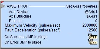
The red triangle in the upper left corner of the status display indicates this is a Fully Asynchronous instruction.
The gray triangle at the right end of the input leg indicates the input is edge-triggered, meaning this instruction will execute each time the input logic transitions from OFF to ON.
See Also
AXSETPROP - Axis Set Properties
AXRSTFAULT - Reset Axis Limit Fault
AXSCRIPT - Run a Sequence of Axis Commands
AXHOME - Axis Perform Home Search
AXPOSTRAP - Axis Move to Position Using Trapezoid
AXPOSSCRV - Axis Move to Position Using S-Curve
AXVEL - Axis Set Velocity Mode
AXGEAR - Axis Electronic Gearing
AXFOLLOW - Axis Position Following with Offset
AXCAM - Axis Electronic Camming
Related Topics
Example