Topic: DMD0410

BRX Axis / Pulse Outputs
The BRX PLCs High-Speed outputs (either the on-board High-Speed outputs, or the outputs on a BRX HSIO module (Bx-HSIO1, BX-HSIO2) can be used as pulse outputs which are typically used to send pulse trains to stepper motors or servo motors at a frequency up to 250 kHz. After selecting one of the available Axis / Pulse Outputs the next step is to configure the Name, the operational mode and specify which physical High-Speed outputs the Axis will use.
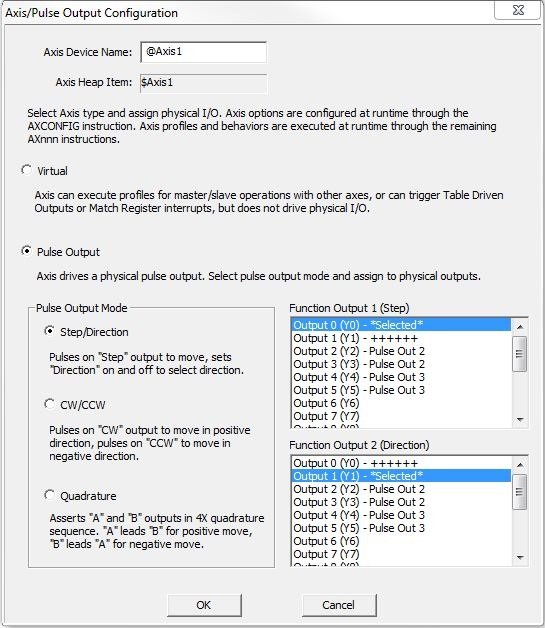
Axis Device Name is a name given to this High-Speed I/O Axis / Pulse Output. This name will also be used as the name of the structure you will use to interact with this Axis in the ladder logic project. The device name can be 1 to 16 characters in length and consist of any combination of alphanumeric characters and underscores ('_', 'a-z', 'A-Z', 0-9), no spaces or punctuation marks are allowed, and must begin with a letter or an underscore.
Axis Heap Item is the name of the associated structure that is automatically created when you configure the Axis / Pulse Output device.
Virtual means the Axis will be available to all instruction that can use an Axis, but no physical outputs have been selected for the Axis to use. This can be useful when designing and testing the movement of an Axis without it actually being connected to actual hardware, or used to generate a source position or velocity value that will be used to coordinate the movements of other Axes in the system.
Enabling the Pulse Output selection means you can now select the operational mode and bind High-Speed outputs to this Axis.
Pulse Output Mode selects one of the following options to specify how the Axis Outputs will operate.
- Step / Direction means output pulses will be on the Step Output, direction is determined by the ON / OFF State of Direction output.
- CW / CCW means pulses on the CW output will move in a positive direction, pulses on the CCW output will move in the negative direction.
- Quadrature means output pulses will be sent on 4X Quadrature mode. When A leads B direction is positive. When B leads A the direction is negative.
The Pulse Output Mode selection will determine how many actual outputs are required for that function. The hardware outputs will be selected in the Function Output boxes to the right.
Function Output 1 selects which of the unused High-Speed I/O outputs to use as the Step / CW / A output.
Function Output 2 selects which of the unused High-Speed I/O output to use as the Direction / CCW / B output. As the outputs are selected you will see one of the following text appear to the right of a selection:
**CONFLICT** indicates the currently selected output is already being used by another output on the same Axis.
*Selected* indicates the currently selected output.
++++++: for pulse output modes that require multiple outputs, this indicates the current selection for the other required outputs.
Pulse Output # indicates the output is already being used by another Axis.
PWM # indicates the output is already being used as a Pulse Width Modulated Output.
Table # means indicates the output is already being used as a Table Driven Output.
See Also:
BX-HSIO1 / BX-HSIO2 High-Speed I/O Modules
BRX Pulse Width Modulated Outputs
Related Topics:
AXSETPROP - Axis Set Properties
AXRSTFAULT - Reset Axis Limit Fault
AXSCRIPT - Run a Sequence of Axis Commands
AXHOME - Axis Perform Home Search
AXVEL - Axis Set Velocity Mode
AXGEAR - Axis Gear High Speed Register
AXFOLLOW - Axis Follow High Speed Register