Topic: DMD0376

BRX Interrupt Triggers
A PLC normally reads its inputs at the top of the scan and writes its outputs at the bottom of the scan, the ladder logic is solved after the inputs are read and the outputs are written. Because the PLC can change the amount of work it does from scan to scan, the PLC's scan time will also change accordingly, which will directly affect the frequency that inputs can be read and outputs can be written.
BRX MPU use interrupts to do work that has to occur regardless of variations in the PLC scan time. Discrete Input Interrupts can be used to respond to transitions of discrete inputs that occur during a PLC scan. Value Match Interrupts can respond to specific values in specified registers. Timed Interrupts can be used to turn discrete outputs ON or OFF at specified regular intervals or at a specified delay time.
When an interrupt occurs the BRX MPU will run a specified code block called an Interrupt Service Routine (ISR). BRX MPUs implement these interrupt events by creating an Interrupt Trigger that specifies the type of trigger, the required triggering conditions, and which Interrupt Service Routine to execute when that trigger is fired. The Setup Interrupt Triggers dialog creates the default settings for the Interrupt Triggers which are loaded each time the BRX MPU transitions from PROGRAM to RUN mode. These settings can be changed at runtime with the Interrupt Configuration Editor (INTCONFIG) instruction.
Setup Interrupt Triggers
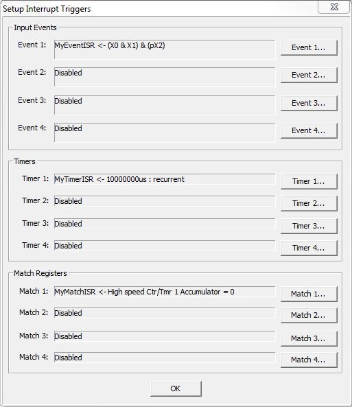
There are the following three types of Interrupt triggers:
Input Event Trigger triggers on the state or transition of one or more of the on-board discrete inputs. There can be up to 4 Input Event triggers defined for the MPU itself and 4 for each BRX HSIO module. Click one of the four "Event x" buttons to open the Setup Input Event editor to specify the inputs used, the conditions to fire the trigger, and the ISR to execute when it fires.
Timer based Trigger triggers on a hardware timer. There can be up to 4 Timer triggers defined for the MPU itself and 4 for each BRX HSIO module. Click one of the four "Timer x" buttons to open the Setup Timer editor to specify the timer mode and duration to fire the trigger, and the ISR to execute when it fires.
Register Match Trigger triggers on the successful comparison of a value when the BRX High-Speed I/O is configured for encode input and / or pulse output. There can be up to 4 Match Register triggers defined for the MPU itself and 4 for each BRX HSIO module. Click one of the four "Match x" buttons to open the Setup Match Register editor to specify the match register to use, the comparison value to fire the trigger, and the ISR to execute when it fires.
To make sure that all of the 12 potential interrupt triggers has an equal chance to run, the interrupt processor uses a round-robin scheme to determine which interrupt will run next. The order is Event 1, Timer 1, Match 1, Event 2, Timer 2, Match 2, Event 3, Timer 3, Match 3, Event 4, Timer 4, Match 4.
Setup Input Event
BRX MPUs can use their on-board discrete inputs or the inputs on BRX HSIO modules (BX-HSIO1, BX-HSIO2, HSIO4) to trigger the execution of an Interrupt Service Routine. The triggering Event is constructed from the input's current state of the selected input (a High / Low Level), and transitions between states of the selected input (a Rising / Falling / Either Edge).
The AND selections are states, and should be considered preconditions; OR selections are transitions or edges, and should be considered triggers. An Input Event must contain at least one trigger (one of the OR selections) but does NOT have to contain any preconditions (one of the AND selections). Any time all of the Level Events (AND selections) are true, any of the Edge Events (OR selections) will cause the associated Interrupt Service Routine to run.
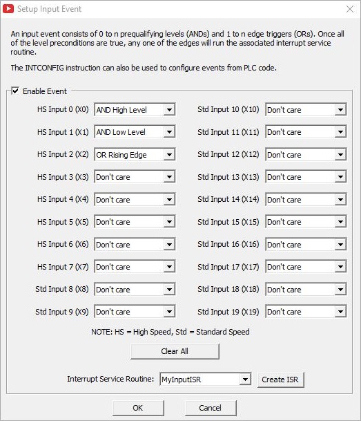
Enable Input Event is the "master" enable for this event, enable this selection to "arm" this event.
Input 0 - Input 19: when using the inputs on a BRX MPU, there are potentially 20 discrete inputs (0 - 19) that can be used in the trigger event depending on which MPU model is being used. Remember that only the first 10 on-board inputs are High-Speed inputs (denoted as HS on the dialog); any other inputs are standard speed (denoted as Std on the dialog). When using one of the BRX HSIO modules (BX-HSIO1, BX-HSIO2, HSIO4), there are 8 discrete inputs available for use in the trigger. All 8 of these inputs are High-Speed inputs.
The High-Speed discrete inputs allow for much quicker response times than the standard speed inputs. And while it's possible to select the standard speed inputs for use in the input event, the use of the High-Speed inputs will provide the responsiveness that is typically expected when using hardware interrupts. If the application requires both level inputs and edge inputs, it is possible that the standard speed inputs could work acceptably well as the level inputs, leaving the High-Speed inputs available for edge inputs which are required to be more responsive.
Don't Care (default) means this input is not part of the triggering event.
AND High Level: if this Input's level is HIGH (input is ON) this part of the trigger event is TRUE.
AND Low Level: if this Input's level is LOW (input is OFF) this part of the trigger event is TRUE.
OR Rising Edge: any time this Input's state changes from OFF to ON this part of the trigger event is TRUE.
OR Falling Edge: any time this Input's state changes from ON to OFF this part of the trigger event is TRUE.
OR Both Edges: any time this Input's state changes from OFF to ON then back to OFF this part of the trigger event is TRUE.
Clear All will set all of the available Input entries back to the default setting of Don't Care.
Interrupt Service Routine is the name of the Interrupt Service Routine to execute when the Input Event trigger happens.
Click Create ISR to create a new Interrupt Service Routine for this Input Event to execute. The ISR Code Block Configuration dialog will open where you can enter the name for the new ISR.
Click OK to save the Event configuration, or Cancel to close this dialog and lose any changes that were made.
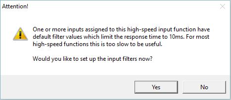
Note: the default Input Filter value of 10ms (25Hz / 750000 clocks) is not an appropriate value when the High-Speed I/O inputs are used for an interrupt signal. You will want to change the Input Filter value to a faster response time (lower filter value) to allow the interrupt signal to work as quickly as expected. Do-more Designer will display the following message box any time one of the High-Speed I/O inputs is selected for use as an interrupt without changing the default filter time.
After an Event Trigger is setup its configuration will be displayed on the main dialog in shorthand form, similar to the example below.
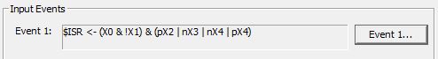
The leftmost group in parentheses contains the level (AND) inputs; the rightmost group contains the edge (OR) inputs. The above example shows (X0 High and X1 Low) and (rising edge X2 or falling edge X3 or either edge X4 ). The shorthand uses the following symbols:
the & indicates a logical AND operation
the | indicates a logical OR operation
the ! indicates Low level (no ! indicates High level)
the p indicates a rising edge
the n indicates a falling edge
Setup Timers
BRX MPUs and BRX HSIO modules (BX-HSIO1, BX-HSIO2, HSIO4) use a hardware timer to run an Interrupt Service Routine in situations where you need an action to occur at regular intervals and not be affected by variations in the PLC scan time. For example, situations that require actions occur at precise repeating intervals, or actions that occur after a precise amount of delay time.
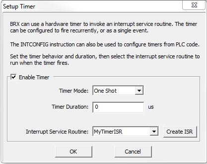
Enable Timer is the "master" enable for this timed event, enable this selection to allow the Timer to run.
Timer Mode specifies how the Timer will operate once it is enabled.
One Shot: each time the Enable Timer is set ON, the Timer will run, and once it expires the configured ISR will run one time. To run the Timer Event again, you must disable then re-enable the Timer Event with an INTCONFIG - Interrupt Configuration Editor instruction.
Recurrent: once the Enable Timer is set ON, the Timer will run, and once the Timer expires the configured ISR will run one time and if the Enable Timer is still ON, the Timer will automatically run again.
Timer Duration is the number of microseconds for the timer to run, This can be any constant value between 0 and 2,147,483,647.
Input Service Routine is the name of the Interrupt Service Routine to execute when the Timer expires.
Click Create ISR to create a new Interrupt Service Routine for this Timed Event to execute. The ISR Code Block Configuration dialog will open where you can enter the name for the new ISR.
Click OK to save the Timer configuration, or Cancel to close this dialog and lose any changes that were made.
Setup Match Registers
When one of the BRX CPU's on-board a High-Speed I/O inputs or one of the inputs on a BRX HSIO module (BX-HSIO1, BX-HSIO2, HSIO4) is configured for high speed counting, a register match operation can be used to generate a Match Register Event to trigger the execution of an Interrupt Service Routine. Once enabled, the ISR will be run each time the comparison operation transitions from "not a match" to "is a match".
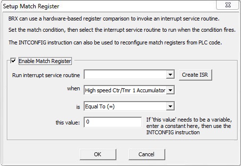
Enable Match Register is the "master" enable for this register match event, enable this selection to allow the comparison to be made.
Run Input Service Routine is the name of the Interrupt Service Routine to execute once the register match is successful.
Click Create ISR to create a new Interrupt Service Routine for this Match event to execute. The ISR Code Block Configuration dialog will open where you can enter the name for the new ISR.
When specifies which of the High-Speed I/O input or output locations to use in the comparison. Choose from the following:
High-Speed Ctr / Tmr 1 Accumulator
High-Speed Ctr / Tmr 2 Accumulator
High-Speed Ctr / Tmr 3 Accumulator
Pulse Output 2 Position
Pulse Output 3 Position
Is specifies the math operator to use when preforming the comparison. Choose from the following:
Equal To
Greater Than or Equal To
Less Than or Equal To
This Value specifies the 32-bit signed decimal constant value to compare to the register contents. This can be any constant value between -2147483648 and 2147483647. Note: if 'this value' needs to be a variable that can be changed at runtime, instead of entering a variable memory location for this parameter, leave this value as a constant and use the INTCONFIG - Interrupt Configuration Editor instruction to change this value at runtime.
Click OK to save the Match Register configuration, or Cancel to close this dialog and lose any changes that were made.
See Also:
INTCONFIG - Interrupt Configuration Editor
INTDECONFIG - Deconfigure Interrupt
INTSUSPEND - Suspend Interrupts
Related Topics:
BRX Interrupt Triggers
BRX Pulse Width Modulated Outputs