Topic: DMD0247

CPU Configuration
This page of the System Configuration dialog provides the selections necessary to configure the on-board hardware of a Do-more CPU. This includes the following:
Serial Port Configuration sets the operational mode of the on-board serial port.
POM (Pluggable Option Module) Configuration sets the operational parameters for optional POM devices for BRX PLCs.
Watchdog Timer sets the default value of the Software Watchdog Timer.
Internal Ethernet Port sets the TCP/IP Address and the Node ID, Name and Description, and an alternate UDP Port number for use with Port Forwarding.
TimeSync allows Ethernet-equipped Do-more CPUs to automatically synchronize their internal clocks.
Default TLS TimeSlice sets the amount of time to allow each TLS encrypted connection to work on each PC scan.
Modbus/TCP Server Configuration will enable / disable the built-in Modbus/TCP Server's use of the on-board Ethernet port.
EtherNet/IP Server / Adapter Configuration will enable / disable the built-in EtherNet/IP Explicit Message Server and the Implicit Adapter's use of the on-board Ethernet port or BX-P-ECOMEX.
Enable Web Server on Ethernet-equipped BRX CPUs (BX-DM1E-xx), this will enable both the on-board web server and the REST API that it uses.
Server Whitelist on Ethernet-equipped BRX CPUs, this will allow only the specified network devices access to various communication servers on the BRX PLC.
On-board Serial Port Configuration
The Serial Port Mode configuration selects the operational mode for the on-board serial port of the Do-more CPU. The selections are mutually exclusive, meaning that the on-board serial port can only operate in one of the following modes at any given time. The operational mode selection will determine the Device and the associated structure that are created to give your project runtime access to the serial port. Setting the port's parity, baud rate, slave ID, etc. can be done when the operational mode is selected or they can be set at runtime with the Setup Serial Port (SETUPSER) instruction.
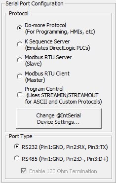
Protocol
Do-more Protocol (For programming, HMIs, etc.)
Select this option to have the serial port use the Do-more native protocol. This protocol is used when the port is used as a programming port for Do-more Designer programming software, or when the port is used with an HMI such as a C-More panel, Point of View software, etc. that is configured to use "Automationdirect Do-more Serial" protocol.
K-Sequence Server (Emulates DirectLOGIC PLCs)
Select this option to have the port use K-Sequence protocol to allow third-party devices that communicate via K-Sequence protocol to read and write the DirectLOGIC protocol-specific memory in the Do-more CPU. K-Sequence is a proprietary protocol used by Automationdirect (Koyo) hardware.
K-Sequence Protocol Settings : configuration settings used when this Device responds to K-Sequence Client requests:
Station sets the ID of the K-Sequence Server Device, this can be any constant from 1 to 90.
Devices that connect with the K-Sequence protocol will only have access to the following blocks of memory (these blocks are numbered in octal):
Block Name
Description
DLX
Inputs
DLX0 - DLX777
DLY
Outputs
DLY0 - DLY777
DLC
DLC0 - DLC777
DLV
DLV0 - DLV3777
Note: The size of the memory blocks available to the K-Sequence driver can be changed in the Memory Configuration.
Modbus RTU Server (Slave)
Select this option to have the serial port use Modbus protocol to allow a third-party device that communicates via Modbus/RTU protocol to read and write the Modbus protocol-specific memory in the Do-more CPU.
Modbus Protocol Settings are the configuration settings used when this Device responds to Modbus/RTU Client requests:
Unit ID sets the Unit ID of the Modbus/RTU Server Device, this can be any constant from 0 to 255.
Devices that connect with the Modbus/RTU protocol will only have access to the following blocks of memory (these blocks are numbered in decimal):
Block Name
Description
Default Range
MI
Modbus Inputs
MI0 - MI1023
Modbus Control Relays
MC0 - MC1023
MIR0 - MIR2047
MHR0 - MHR2047
Note: The size of the memory blocks available to the Modbus/RTU driver can be changed in the Memory Configuration.
The Modbus/RTU Server (Slave) supports the following function codes:
Description
1
2
3
4
Read input Registers
5
6
7
15
16
22
Mask Write Register
Modbus RTU Client (Master)
Select this option to allow the on-board serial port to be used by the Modbus Network Read (MRX) and Modbus Network Write (MWX) instructions. If this option is selected the MRX and MWX instructions can select @IntSerModbusClient as a target Device.
Modbus Protocol Settings are the configuration settings used when this Device is used in a Modbus Network Read (MRX) or Modbus Network Write (MWX) instruction:
Timeout is the amount of time (in milliseconds) the instruction should wait for the remote Modbus RTU Server to respond, this can be any constant from 0 to 32767.
Retries is the number of times the instruction should retry the communication with the remote Modbus RTU Server, this can be any constant from 0 to 255.
Inter-packet Delay is the amount of time (in microseconds) that will be placed between the Modbus RTU packets as they are sent. This can be any be any constant between 0 and 65535. The inter-packet delay creates the required "dead time" on the wire that Modbus uses to frame a packet. The Modbus specification requires this value to be a minimum of 3.5 characters times (based on baud rate). If the value entered is smaller than the required time, the Modbus RTU Client will use the minimum required time instead of the value that is entered. If the value entered is larger than the required time, the value entered will be used.
Use this formula to calculate the inter-packet delay (in microseconds) based on baud rate:
( 3.5 * (number of bits in a character / baud rate) ) * 1,000,000
For example: using a 10-bit character (1 start bit, 8 data bits, no parity bit, and 1 stop bit) at 19200 baud:
( 3.5 ( 10 / 19200 ) ) * 1,000,000 = 1823 microseconds
Program Control (Uses STREAMIN / STREAMOUT for Custom Protocols)
Select this option to allow the on-board serial port to be used by the Stream In Data from Device (STREAMIN) and Stream Out Data to Device (STREAMOUT) instructions for sending and receiving ASCII data, or implementing custom protocols. Once configured this way the STREAMIN and STREAMOUT instructions will have the option of selecting the @IntSerial as a target Device.
Device Name displays the name of the on-board serial port. To change the device's name use the Device Configuration dialog.
Change @IntSerial Device Settings
After selecting the desired operational mode, click the Change @IntSerial Device Settings ... button to change the on-board serial port's hardware configuration.
Baud Rate : 115200, 57600, 38400, 19200, 9600, 4800, 2400, 1200, 300
Data Bits : 7, 8
Transmit Control determines when data will be transmitted.
Unconditional : data will be transmitted as soon as it reaches the output buffer.
Wait for CTS : data will be transmitted when the CTS line is asserted.
Delayed 5ms, Delayed 50ms, Delayed 250ms, Delayed 500ms : after data reaches the output buffer, the RTS line will be asserted, and the transmitting of the data will be delayed by the selected number of milliseconds.RTS Control selects how the RTS line will operate
Follows Transmitter puts the RTS line is under the control of the transmitter.
Manual allows programmatic control of the RTS line through the structure member IntSerial.RTS.
Off forces the RTS line to always be OFF.
On forces the RTS line to always be ON.
Port Type
On BRX CPUs the on-board serial port can be configured to operate as either an RS-232 port (the default) or an RS-485 port).
- select RS232 (Pin 1: GND, Pin 2: RX, Pin 3: TX) to have the port operate in RS-232 mode.
- select RS485 (Pin 1: GND, Pin 2: D+, Pin 3: D-) to have the port operate in RS-485 mode.
If RS-485 mode is selected, the Enable 120 Ohm Termination will enable the on-board 120 Ohm termination resistor between D+ and D- connections. The termination resistor is typically enabled on the RS-485 device at each end of the cable; RS-485 devices in the middle of the cable leave the termination resistor disabled.
Default Watchdog Timeout
The Software Watchdog Timeout specifies the maximum amount of time (in milliseconds) to allow for a single scan in the CPU to complete. If this value is exceeded, the CPU will immediately transition to STOP mode, an error message will appear in the System Information log, and the ERR LED (H2-DM1x) or STAT LED (T1H-DM1x) on the front of the CPU will be ON.
The Default Watchdog Timeout value is written to the system watchdog timer location $WatchdogTimeVal (DST23) on each STOP-mode to RUN-mode transition. This value can be changed at runtime by moving a new value into this location.
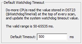
Default Timeout specifies the number of milliseconds to use as the default watchdog timeout. This can be any constant value between 50 and 65535.
Note: CPUs also have a Hardware Watchdog Timer that is used to put the PLC into a safe mode if the operating system ever stops running for more than 2 seconds. Follow this link for details on Configuring the Hardware Watchdog Timer.
Internal Ethernet Port
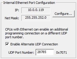
IP: and Net Mask: fields show the currently configured TCP/IP Address and Subnet mask respectively. Clicking Configure will open the Setup Node And IP Address dialog where this configuration can be changed.
Note: Configure... will be disabled if the Do-more Project is offline (because the TCP/IP configuration is NOT stored as part of the project), or if the Do-more project is for a DM-SIM (because the Simulator uses the TCP/IP setup of the PC that running the Simulator and that can't be changed by Do-more Designer).
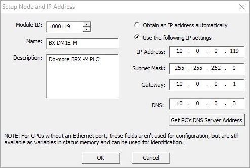
Module ID can be any positive constant number.
Name can be any 255 character combination of alphanumeric and punctuation characters. The Module ID and Names entered must be unique on the network where the CPU will be connected.
Description can be any 255 character combination of alphanumeric and punctuation characters.
The IP Address configuration can be set in one of two ways:
- Enable the Obtain an IP Address automatically (use DHCP) option to have the on-board Ethernet port obtains its IP Address, Subnet Mask and Gateway Address from a DHCP server. Note: the on-board Ethernet port (@IntEthernet) did not support DHCP until Do-more Technology Version 2.8.
The IP Address configuration can be entered as a static address in the following four fields:
IP Address can be any valid TCP/IP Address. The IP Address entered must be unique on the network where the CPU will be connected.
Subnet Mask can be any valid TCP/IP Subnet Mask.
Gateway can be any valid TCP/IP address of a network Gateway.
DNS can be any valid TCP/IP address of a DNS server on the network. Click the Get PC's DNS Server Address to read that information from the PC running Do-more Designer.
Once the IP Address information has been set by either of the above methods, that information will be reflected in the system-memory locations $IPAddress (DST18), $NetMask (DST19), $Gateway (DST20). For Do-more CPUs that do not have an on-board Ethernet port, these fields are not used for configuration purposes, but these fields can still be used for identification by manually storing identifying values there.
When Do-more Designer establishes a programming session with a Do-more CPU it uses the IP address assigned to the CPU and the port's fixed port number of 28784 (0x7070). If the situation arises, the Ethernet-equipped Do-more CPUs can be configured to allow a Do-more Designer programming session to be established using the same IP address but on an alternate port number.
Check the Enable Alternate UDP Connection selection to enable processing of packets from the following additional UDP Port Number:
UDP Port Number is the alternate UDP Port Number that Do-more Designer will be using. This can be any decimal value between 5000 and 65535, except for 28784 (the port number already used by Do-more Designer). The hexadecimal equivalent of the specified port number is displayed to the right.
A common situation where this is utilized is allowing remote computers
(for example, computers on the Internet) to connect to a Do-more CPU
on a private, local-area network. The network administrator configures
the Internet Gateway so that an external network address / port number
request is routed to a specific network address / port number on the internal,
private network (this is typically referred to as Port Forwarding![]() A network setup that redirects a communication request from one address and port number combination to another while the packets are traversing a network gateway, such as a router or firewall.). External hosts must know the IP address of the Internet
Gateway and the port number assigned to the target device on the internal
network.
A network setup that redirects a communication request from one address and port number combination to another while the packets are traversing a network gateway, such as a router or firewall.). External hosts must know the IP address of the Internet
Gateway and the port number assigned to the target device on the internal
network.
Using the example configuration table for an Internet Gateway shown above, setting up Do-more Designer to access the Do-more CPUs that are configured to use a Secondary Ethernet Connection requires the following steps:
-
Edit the DmDesigner.Ini file to enable the option that allows the Link to contain a user-specified IP port number that Do-more Designer will use to establish the session.
-
Begin by double-clicking the "DmDesigner.Ini" selection in the Applications section of the Launchpad. This will open DmDesigner.Ini in Windows Notepad.
-
Search for the ";UDPPortNumEnable=1" entry in the "[DevEther.Dll]" section.
-
Remove the leading ";".
-
Close and Restart Do-more Designer to re-read the new DmDesigner.Ini file.
-
Create a new link in Do-more Designer for the CPU, the Link Editor must be used to manually specify all of the connection parameters - the Link Wizard will not work to create this link.
-
On the PLC tab select the Do-more Series and the CPU type from the Family and Type groups
-
On the Port tab select Devices -> Ethernet, Transport Protocol -> UDP/IP, then click the Advanced Settings button and make changes to the following two entries:
-
Timeout: the default value of 250 ms is typically not high enough for connecting over the Internet. Use the following steps to determine an initial Timeout value:
-
Open a DOS Command Prompt (Start --> Programs --> Accessories --> Command Prompt)
-
Ping the IP address of the Internet Gateway device, for example "ping 12.69.41.166"
-
Increase the Maximum timeout value by at least 50% and enter this number as the "Timeout" setting.
-
UDP Port Number: this is the same number configured as the UDP Port Number in the Secondary Ethernet Connection option
-
On the Protocol tab make sure the Protocols -> Do-more is selected.
-
Click Auto to test the current link parameters. There will be an audible beep if the link test is successful. If the link test is NOT successful, increase the Timeout value. and try again.
-
Repeat steps 3 through 7 to create new Do-more Designer Links for the remaining CPUs.
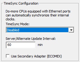
TimeSync Configuration
The TimeSync Configuration option allows the Ethernet-equipped Do-more CPUs on the same network to automatically synchronize their internal real-time clocks. A typical network will have one Do-more CPU configured as a TimeSync Server, one or more CPUs configured as TimeSync Alternates, and the remaining CPUs configured as TimeSync Clients.
TimeSync packets are generated by the Do-more CPU that is operating as a TimeSync Server. These packets are automatically sent by the TimeSync Server at the specified Update Interval and any time the real-time clock on the TimeSync Server is manually changed, either manually by Do-more Designer, or by a NETTIME (SNTP Client) instruction in the CPU. The TimeSync packet contains the current time from the TimeSync Server and the Update Interval so that Clients and Alternates will know when to expect the next TimeSync packet.
Note:
This feature uses TCP/IP broadcast packets on port number 123 to synchronize
the real-time clocks of the Clients and Alternates, which means that only
Do-more CPUs within the TimeSync Server's Broadcast Domain![]() A broadcast domain is a logical network segment in which any device connected to the network can directly transmit to any other on the domain without having to go through a routing device. These are typically very basic networks that use hubs rather than switches or routers. A special broadcast address consisting of all 1s is used to send frames to all devices on the network.
can be synchronized
A broadcast domain is a logical network segment in which any device connected to the network can directly transmit to any other on the domain without having to go through a routing device. These are typically very basic networks that use hubs rather than switches or routers. A special broadcast address consisting of all 1s is used to send frames to all devices on the network.
can be synchronized
A Do-more CPU can be configured to operate in a TimeSync network in one of the following possible modes:
Disabled will disable the TimeSync feature in this CPU, meaning the CPU's real-time clock will NOT be synchronized by a TimeSync Server. This is the default configuration.
Client will enable TimeSync and the CPU will process TimeSync messages that are sent from a TimeSync Server. Each time a Client receives a TimeSync message it will update it's real-time clock with the real-time clock information in the TimeSync packet, set it's Status Bit $TimeSynced (ST23) ON which indicates that the clocks have been synchronized, and begin timing down from the Update Interval so the Client will know when to expect the next TimeSync packet.
Server will enable TimeSync and this CPU will generate TimeSync messages for other CPU on the network that are configured as Clients and Alternates. At each Update Interval or any time the Server's real-time clock is changed, a TimeSync Server will broadcast three TimeSync messages at five second intervals - three messages are sent to make sure that the Clients and Alternates receive at least one of the messages.
Alternate will enable TimeSync and this CPU will normally function as a TimeSync Client but will promote itself to a TimeSync Server if there are no TimeSync packets received within the Update Interval. An Alternate will begin the process of promoting itself to a Server 15 seconds after the Update interval has expired.
The Update Interval is used in the following three ways:
By a TimeSync Client: once a Client has its time synchronized, it sets its own $TimeSynced (ST23) status bit and will begin using the Update Interval value as a countdown timer to know when to expect the next TimeSync packet. If that packet is not received before the Update Interval expires the CPU will reset it's $TimeSynced status bit to indicate that the time is no longer synchronized.
By a TimeSync Alternate: once an Alternate has its time synchronized, it sets its own $TimeSynced (ST23) status bit and will begin using the Update Interval value as a countdown timer to know when to expect the next TimeSync packet. If the next packet is not received before the Update Interval expires the Alternate will begin the process of promoting itself to a TimeSync Server.
By a TimeSync Server: sets the frequency that TimeSync packets are broadcast on the network.
Enable Use Secondary Adapter (ECOMEX) to route the TimeSync packets through the BRX CPU's Secondary Ethernet port (BX-P-ECOMEX POM ) instead of the on-board Ethernet port.
Default TLS TimeSlice Configuration
When a BRX CPU uses TLS to negotiate with a server to establish an encrypted session, the amount of time it takes to establish this connection varies, but it is most always several seconds of time. The CPU doesn't stop its normal scan processing while working on establishing the connection, the CPU allots a small portion of time (called the TLS Timeslice) on each PLC scan to each device that is trying to establish an encrypted connection. Increasing this value can allow the TLS process to complete sooner, but at the cost of increasing the PLC's scan time.
The TLS Timeslice value is applied to each client device or instruction that is trying to establish an encrypted connection, for example, if a Send EMAIL instruction and an MQTT Publish instruction are both executing, they will both get the full TLS Timeslice value on each scan.
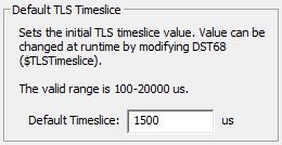
The Default Timeslice value is be used by the TLS encryption engine each time the PLC powers up and goes into RUN mode. This value can be changed while the CPU is in RUN mode by changing the value in $TLSTimeslice (DST68).
The following use TLS to establish an encrypted connection:
SMTP (Send Email) Client Device
MQTT (Publish / Subscribe) Client Device
Modbus/TCP Server Configuration
The Modbus/TCP Server Configuration options are used to setup and optimize the Modbus/TCP Server device driver in CPUs that have an on-board Ethernet port. The Modbus/TCP Server can support up to 16 concurrent sessions with Modbus/TCP Clients.
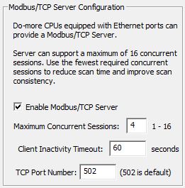
The Enable Modbus/TCP Server option completely enables or completely disables the CPU's Modbus/TCP Server device driver. If this option is unchecked, the Modbus/TCP Server device driver is disabled, meaning the CPU will not respond to any Modbus/TCP Client requests.
The Maximum Concurrent Sessions value specifies how many concurrent Modbus/TCP Server connections the device driver can handle. Establishing a Modbus/TCP Server session requires processing time which will inevitably impact the scan time. If there are more Modbus/TCP Clients requesting connections than there are concurrent sessions available, part of this processing includes shutting down the oldest session so that a new session can be opened. The need to forcibly close sessions so that new ones can be opened can be minimized by setting this value to the maximum number of individual Modbus/TCP Clients that will be connecting to this CPU at any given time. This can be any constant value between 1 and 16.
The Client Inactivity Timeout specifies how much time (in seconds) to wait before closing the connection for a Modbus/TCP Client that has stopped communicating. This can be any constant value between 0 and 65535.
TCP Port Number (502 is default) specifies the TCP port number the Modbus/TCP Server device driver will accept connections on. The default value of 502 is the industry standard, and rarely will this value need to be changed. This can be any constant value between 0 and 65535.
Devices that connect with the Modbus/TCP protocol will only have access to the following blocks of memory (these blocks are numbered in decimal):
Block Name
Description
Default Range
MI
Modbus Inputs
MI0 - MI1023
MC
Modbus Control Relays
MC0 - MC1023
MIR
Modbus Input Registers
MIR0 - MIR2047
MHR
Modbus Holding Registers
MHR0 - MHR2047
Note: The size of the memory blocks available to the Modbus/TCP driver can be changed in the Memory Configuration.
The Modbus/TCP Server (Slave) supports the following function codes:
Function Code
Description
1
Read Coils
2
Read Discrete Inputs
3
Read Holding Registers
4
Read input Registers
5
Write Single Coil
6
Write Single Register
7
Read Exception Status
15
Write Multiple Coils
16
Write Multiple Registers
22
Mask Write Register
Server Whitelist (Only available on BRX CPUs)
The function of a Whitelist is to allow access to resources on a device only to network entities that have been previously identified, and by doing so, exclude access to those resources from network entities NOT previously identified. On a BRX CPU, this means giving explicit access to the various Ethernet network communication servers (programming, Modbus/TCP, Ethernet /IP, etc.) only to network devices that are specified in the whitelist for that service. Using a whitelist is a good option for restricting access to the otherwise unsecured communication servers (protocols) in a BRX CPU.
By default, the whitelist process is disabled, meaning all of the CPU's communication servers will accept valid communication requests from any client on the network. Check the Enable Server Whitelist checkbox to turn ON the CPU's white-listing process.
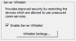
Enabling the server whitelist alone does not do any meaningful work; it only enables the whitelist processing. You must add entries to the various server's protocol whitelists before any allow / deny access of that server will take place. Clicking the Whitelist Settings... button will open the following dialog where the details of which communications have whitelest processing enabled, and for those that do, which IP address will be allowed to communicate with those servers.
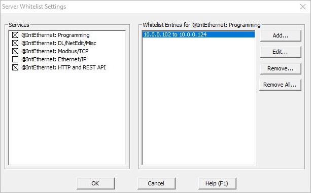
The default configuration has none of the whitelists enabled for any of the communication Services. The process of white-listing consists of enabling the whitelist for one of the Services listed, then adding one or more clients ( by TCP/IP address ) to the Whitelist Entries for that Service. There are currently 5 Services that can have a whitelist:
The Programming service handles connections to clients that establish a session using Do-more protocol, this includes connections from Do-more Designer, connections from C-More HMIs, and connections from other Do-more CPUs using Do-more Network Read (RX) and / or Do-more Network Write (WX) instructions.
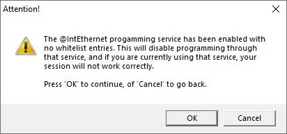
Note: if the whitelist for Programming is enabled but no entries have been added to the whitelist, the following warning is displayed:
DL / NetEdit / Misc are the services that handle connections from DirectLOGIC PLCs with an ECOM / ECOM100 modules using DirectLOGIC Network Read (DLRX) and / or DirectLOGIC Network Write (DLWX) instructions. They also handle discovery and configuration requests from NetEdit, and networking services such as Peerlink.
The Modbus/TCP service handles connections from Modbus/TCP Clients.
The EtherNet/IP service handles connections from EtherNet/IP Clients.
The HTTP and REST API services handle connections from HTML clients (web browsers, web apps, etc.).
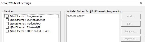
There are three possible entries in the Whitelist Entries section:
Seeing *Service Open* for a service means there is no whitelist processing being done for the service.
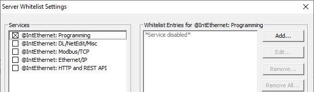
Seeing *Service Disabled* means the Service has whitelist processing enabled, BUT, there are NO entries in the whitelist. Doing this effectively disables the Service from being accessed by any Ethernet network clients. This is an acceptable configuration if the point is to completely disable one of the Services.
Seeing an IP address (or range of IP Addresses) means the Service has whitelist processing enabled, and only communication requests from the listed IP Address (or range of addresses) will be allowed through to the communication service.
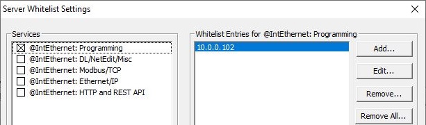
To add one or more clients for a specific service, click on the box to the left of the service and click the Add button :
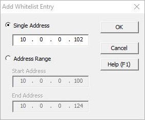
To whitelist a single device, select Single Address and enter the TCP/IP address of the client. To whitelist multiple devices within a range of TCP/IP addresses, select Address Range and enter the first and last TCP/IP address of the range of clients.
See Also:
CPU Configuration
EtherNet/IP Server / Adapter Configuration
Ethernet I/O Master Configuration
Modbus I/O Scanner Configuration