Topic: DMD0248

Device Configuration
Devices are pre-configured interfaces that provide programmatic access to system resources. Additional user configuration of the devices, for example baud rates for serial ports, is provided for in this dialog. Some devices are automatically created - for example @UserLog and @DMLogger - and although they are listed here, they cannot be deleted or edited.
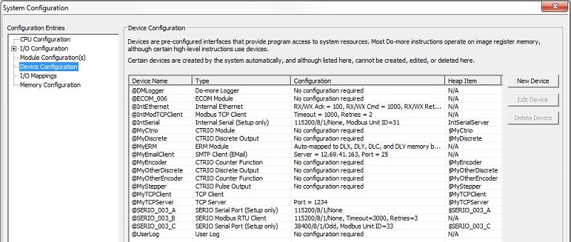
The Device Name column displays the current name of the device, it is this name that is referenced in the instructions that target the Device.
The Type column displays the driver type used for the Device. '(Setup only)' is used to denote Devices that are data servers, that is, they are NOT used as target device in instructions.
The Configuration column displays the current configuration for the Device. 'No configuration required' is used to denote Devices that have a fixed configuration.
The Heap Item column displays the Heap Item that is used for programmatic access to the Device.
Add a New Device
The three buttons at the right allow the programmer to modify the current system Configuration by adding, or deleting, or editing Device configurations.
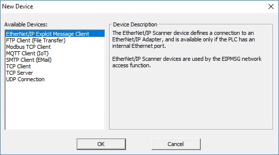
Click the New Device button to invoke the Add Device dialog to create one of the following Devices:
Modbus TCP Client defines a connection to a Modbus TCP/IP Server, and is available only if the CPU has an on-board Ethernet port. Modbus TCP Client devices are used by the Modbus Network Read (MRX) and Modbus Network Write (MWX) instructions. If the project will be using Modbus Read (MRX) instructions to read data from multiple Modbus TCP Servers, the best performance will be had by creating a separate Modbus TCP Client device for each of the Modbus Servers.
MQTT Client (IoT) defines a client-side network connection to an MQTT Broker and is available only if the CPU has an on-board Ethernet port. MQTT Client devices are used by the IoT Publish MQTT Topics (MQTTPUB) and IoT Subscribe to MQTT Topics (MQTTSUB) instructions.
SMTP Client (Email) defines a connection to an Email Server, and is available only if the CPU has an on-board Ethernet port. SMTP Client Devices are used by the Send Email (EMAIL) instruction to specify the target SMTP Server, SMTP port number, and user authentication.
TCP Client defines a client-side TCP socket for a custom TCP/IP protocol (not Modbus/TCP), useful in cases where the CPU needs to send or receive ASCII or binary data. TCP Client devices are only available if the CPU has an on-board Ethernet port. Connections to TCP Servers are created through the Open TCP Connection (OPENTCP) instruction.
TCP Server defines a server-side TCP socket for a custom TCP/IP protocol (not Modbus/TCP) , useful in cases where the controller needs to send or receive ASCII or binary data. TCP Server devices are only available if the CPU has an on-board Ethernet port. The TCP Server is managed through the Start Listening on TCP Port (TCPLISTEN) instruction.
UDP Connection defines a UDP socket for general purpose TCP/IP networking, useful in cases where the CPU needs to send or receive data through a custom streaming protocol. UDP Connection devices are only available if the CPU has an on-board Ethernet port. UDP Connection devices are used by used by the Input Data from Packet Device (PACKETIN) and Output Data to Packet Device (PACKETOUT) instructions.
EtherNet/IP Explicit Message Client is used by an Send EtherNet/IP Message (EIPMSG) instruction to defines a connection to an EtherNet/IP Explicit Message Server, and is available only if the CPU has an on-board Ethernet port. If the project will be using multiple Send EtherNet/IP Message instructions to read data from multiple EtherNet/IP Explicit Message Servers, the best performance will be had by creating a separate EtherNet/IP Explicit Message Client device for each of the Ethernet/IP Explicit Message Servers.
FTP Client (File Transport) defines a connection to a an FTP Server, and is available only if the CPU has an on-board Ethernet port. FTP Client devices are used by the Store File TO Remote (FTPPUT) and Retrieve file FROM Remote (FTPGET) instructions.
Click the Edit Device button to open the edit dialog for the currently highlighted Device.
Click the Delete Device to open deletes the currently highlighted Device.
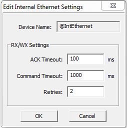
On-board Ethernet Port (@IntEthernet)
Device Name is the logical name
assigned to the Internal Ethernet Device. Device Names can consists of 1 to 16 alphanumeric
characters and must follow Nickname Rules![]() Nicknames can be 1 to 16 characters in length and consist of any combination of alphanumeric characters and underscores ('_', 'a-z', 'A-Z', 0-9), no spaces or punctuation marks are allowed, and must begin with a letter or an underscore..
Nicknames can be 1 to 16 characters in length and consist of any combination of alphanumeric characters and underscores ('_', 'a-z', 'A-Z', 0-9), no spaces or punctuation marks are allowed, and must begin with a letter or an underscore..
RX/WX Settings are configuration
settings used when this Device is used in a DirectLOGIC
Read Network (DLRX) or a DirectLOGIC
Write Network (DLWX) instruction:
ACK Timeout is the number of milliseconds should the instruction wait for an ACK from the remote DirectLOGIC PLC, this can be any constant from 0 to 32767.
Command Timeout is the number of milliseconds should the instruction wait for the remote DirectLOGIC PLC to respond to a data request, this can be any constant from 0 to 32767.
Retries are the number of times should the instruction retry the communication with the remote DirectLOGIC PLC, this can be any constant from 0 to 255.
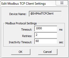
Internal Modbus TCP Client (@IntModbusTCPClient)
Device Name is the logical name
assigned to the Modbus TCP Client Device. Device Names can consists of 1 to 16 alphanumeric
characters and must follow Nickname Rules![]() Nicknames can be 1 to 16 characters in length and consist of any combination of alphanumeric characters and underscores ('_', 'a-z', 'A-Z', 0-9), no spaces or punctuation marks are allowed, and must begin with a letter or an underscore..
Nicknames can be 1 to 16 characters in length and consist of any combination of alphanumeric characters and underscores ('_', 'a-z', 'A-Z', 0-9), no spaces or punctuation marks are allowed, and must begin with a letter or an underscore..
Modbus Protocol Settings are configuration
settings used when this Device is used in a Modbus
Network Read (MRX) or Modbus
Network Write (MWX) instruction:
Timeout is how many milliseconds should the instruction wait for the remote Modbus/TCP Server to respond, this can be any constant from 0 to 32767.
Retries is how many times should the instruction retry the communication with the remote Modbus/TCP Server, this can be any constant from 0 to 255.
Inactivity Timeout is how many seconds after the last communication from the remote Modbus /TCP Server to wait before the controller terminates the connection, this can be any constant from 15 to 3600
Note: There is an additional internal timeout in the TCP stack of 15 seconds that only comes into play if the target TCP Server / Slave is missing from
the network. This internal timeout is used when the TCP connection is being established, which must happen before the Modbus layer transaction can occur.
This internal timeout value cannot be changed. The Timeout, Retries and Inactivity Timeout parameters specified here are all associated with the Modbus
layer (not the TCP layer) and have no effect on the TCP layer timeout.
For Modbus Network Read (MRX) and Modbus
Network Write (MWX) instructions to execute over a TCP connection, the TCP stack must first establish a connection to the target Server / Slave. This
internal timeout of 15 seconds in only used when the TCP stack is determining if the target TCP Server / Slave is available on the network and is independent
of the Timeout and Retries parameters configured here. Once the TCP connection is established, the Device's Timeout, Retries, and Inactivity Timeout parameters
come into play.
On-board Serial Port (@IntSerial) and H2-SERIO or H2-SERIO-4 Module
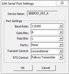
All of the Serial Port Devices in a Do-more PLC have a common Port Settings section with the following configuration options. These serial port configuration can be examined at runtime with the Read Device Register (DEVREAD) instruction, and the configuration can be changed at runtime through the Write Device Register (DEVWRITE) instruction.
Device Name displays the logical name of the serial port Device. Device Names can consists of 1 to 16 alphanumeric
characters and must follow Nickname Rules![]() Nicknames can be 1 to 16 characters in length and consist of any combination of alphanumeric characters and underscores ('_', 'a-z', 'A-Z', 0-9), no spaces or punctuation marks are allowed, and must begin with a letter or an underscore..
Nicknames can be 1 to 16 characters in length and consist of any combination of alphanumeric characters and underscores ('_', 'a-z', 'A-Z', 0-9), no spaces or punctuation marks are allowed, and must begin with a letter or an underscore..
Port Settings select the hardware-specific settings for the specified Serial Port:
115200, 57600, 38400, 19200, 9600, 4800, 2400, 1200
Data Bits
7, 8
1, 2
None, Odd, Even
- Unconditional means data will be transmitted as soon as it reaches the output buffer.
- Wait for CTS means data will be transmitted when the CTS line is asserted.
- Delayed 5ms, Delayed 50ms, Delayed 250ms, Delayed 500ms means after data reaches the output buffer, the RTS line will be asserted, and the transmitting of the data will be delayed by the selected number of milliseconds. These Delayed ... selections require the RTS Control value be set to 0x00 - Follows Transmitter.
RTS Control selects how the RTS line will operate:
- Follows Transmitter means the RTS line is under the control of the transmitter.
- Manual allows programmatic control of the RTS line through the structure member IntSerial.RTS.
- Off forces the RTS line to always be OFF.
- On forces the RTS line to always be ON.
Serial Port as KSequence Server
When the module configuration selects the On-board Serial Port or a port on the H2-SERIO or H2-SERIO-4 as a K Sequence Server, the additional Device configuration option is available:

K Sequence Protocol Settings are configuration settings used when this Device responds to K Sequence Client requests:
Station specifies the ID of the K Sequence Server Device, this can be any constant from 1 to 90. The Station ID can be examined at runtime with the Read Device Register (DEVREAD) instruction, and changed at runtime through the Write Device Register (DEVWRITE) instruction.
Serial Port as Modbus RTU Client
When the module configuration selects the On-board Serial Port or a port on the H2-SERIO or H2-SERIO-4 as a Modbus RTU Client, the additional Device configuration options are available:
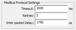
Modbus Protocol Settings are configuration settings used when this Device is used in a Modbus Network Read (MRX) or Modbus Network Write (MWX) instruction:
Timeout is how many milliseconds should the instruction wait for the remote Modbus RTU Server to respond, this can be any constant from 0 to 32767.
Retries are how many times should the instruction retry the communication with the remote Modbus RTU Server, this can be any constant from 0 to 255.
Inter-packet Delay is the amount of time (in microseconds) the Modbus/RTU Client will place between packets as they are sent, this can be any be any constant value between 0 and 65535.
Note: all of the options can be examined at runtime with the Read Device Register (DEVREAD) instruction, and changed at runtime through the Write Device Register (DEVWRITE) instruction.
Serial Port as Modbus RTU Server
When the module configuration selects the On-board Serial Port or a port on the H2-SERIO or H2-SERIO-4 as a Modbus RTU Server, the additional Device configuration option is available:
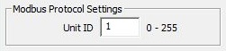
Modbus Protocol Settings : configuration settings used when this Device responds to Modbus RTU Client requests:
Unit ID specifies the Unit ID of the Modbus RTU Server Device, this can be any constant from 0 to 255. The Unit IF can be examined at runtime with the Read Device Register (DEVREAD) instruction, and changed at runtime through the Write Device Register (DEVWRITE) instruction.
MQTT Client (IoT) Device
BRX PLCs with on-board Ethernet Ports can connect to one or more MQTT Brokers, and once connected, these PLCs can publish messages to the Brokers and subscribe to messages from the Brokers. The parameters required to create a connection to a Broker is managed by an MQTT Client (IoT) device.
There is no limit to the number of MQTTPUB instructions that can use a single MQTT Client device, but each MQTT Client device can only provide a subscription space for 100 active topics spread across a maximum of 10 MQTTSUB instructions, for example 2 enabled instruction with 50 Topics each, or 10 enabled instructions with 10 Topics each. To subscribe to more than 100 Topics, create multiple MQTT Client devices to the same MQTT Broker.
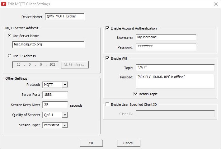
Device Name is the name given to
the MQTT Client device that will be referenced in IoT Publish MQTT Topics (MQTTPUB) and IoT Subscribe to MQTT Topics (MQTTSUB) instructions. Device Names can consists of 1 to 16 alphanumeric
characters and must follow Nickname Rules![]() Nicknames can be 1 to 16 characters in length and consist of any combination of alphanumeric characters and underscores ('_', 'a-z', 'A-Z', 0-9), no spaces or punctuation marks are allowed, and must begin with a letter or an underscore..
Nicknames can be 1 to 16 characters in length and consist of any combination of alphanumeric characters and underscores ('_', 'a-z', 'A-Z', 0-9), no spaces or punctuation marks are allowed, and must begin with a letter or an underscore..
MQTT Server Address selects how the connection to the MQTT Broker will be established.
Select Use Server Name to enter a text string that will be resolved when the MQTTPUB or MQTTSUB instruction is executed.
Select Use IP Address to enter the static IP address of the MQTT Broker. Clicking the DNS Loopkup button will open the IP Address Lookup utility in Do-more Designer that can search for the IP Address assigned to a given MQTT Broker. This requires a functional connection to a DNS Server. Enter the URL for the MQTT server then click the Lookup button. If the operation is successful click the Select button to use the IP address that was found.
Other Settings
Protocol selects whether to use MQTT (unsecured, plain text) or MQTTS (secured, SSL / TLS encryption).
Note: using SSL / TLS encryption is a very CPU intensive operation because of the math involved. Because the CPU must keep the PLC's scan time in check, the SSL encoding is processed as a time-slicing event, meaning that only a portion of each scan time is used to work on the encryption; this prevents the scan time from exceeding the watchdog timer. Processing the encryption can take several seconds depending on the number of security certificates that must be processed and the amount of data being transferred.
The amount of time the CPU allots to processing TLS transactions on each scan is called the TLS Timeslice. This value can be changed on the CPU page of the System Configuration. Increasing this value can allow the TLS process to complete sooner, but at the cost of increasing the PLC's scan time. The Default TLS Timeslice value will be used by the TLS encryption engine each time the PLC powers up and goes into RUN mode. RUN-mode changes to this value can be made by changing the value in $TLSTimeslice (DST68).
Server Port is the IP Port number to use when creating the connection to the MQTT Broker:
1883 is the standard Port number used in connections to unencrypted MQTT Brokers, 8883 is the standard Port number used in connections to MQTT SSL / TLS Brokers. TLS version 1.2 is currently being used.
This Server Port number can be read at runtime with the Read Device Register (DEVREAD) instruction, and changed at runtime through the Write Device Register (DEVWRITE) instruction.
Session Keep Alive assures that the connection is still open and both Broker and client are connected to one another. This interval is the longest possible period of time which Broker and client can endure without sending a message. The client specifies a time interval in seconds and communicates it to the Broker when it establishes the connection. The BRX CPU will send a PING to the broker at 75% of this value if there is no Publish or Subscribe activity to the Broker to keep the session active. The default value of 30 seconds should be sufficient in most instances; the maximum time is 65535 seconds.
Quality of Service is an agreement between sender and receiver of a message regarding the guarantee of delivering a message. BRX CPUs support 2 levels of QoS:
0 (at most once) is the fastest method but it is also the most unreliable transfer mode because the BRX CPU does not wait for the message to be acknowledged by the Broker. With this QoS level the message will be delivered only one time, but possibly not at all, but there is no possibility of duplicate messages.
1 (at least once) means the BRX CPU sends a message and waits for an acknowledgment (PUBACK). This guarantees that the message will be delivered at least once, but it also means that it may be delivered more than once.
Session Type selects whether or not the sever will store data for a broker
Clean means that if the connection between the client and broker is interrupted the client will need to re-subscribe to topics when it reconnects.
Persistent means all information that is relevant for the client is saved by the broker so that if the connection is interrupted the client need only to reconnect to the broker and all of the topic subscriptions are still present and any messages that arrived while the connection was broken are queued by the broker and will be delivered after the connection is remade.
Enable Account Authentication is used if the MQTT Broker requires authentication before it will accept messages.
Username can be 1 to 128 characters.
Password can be 1 to 256 characters. Password can also be empty.
Last Will and Testament
Because MQTT is often used on unreliable networks, the Last Will and Testament (LWT) feature is used in MQTT to notify other clients about a client that disconnects in a less than graceful manner. Each client can specify its Last Will message (a normal MQTT message with Topic, Payload, and , Retain flag) when connecting to a Broker. The Broker will store the message until it detects that the client has disconnected ungracefully. If the client disconnect abruptly, the Broker sends the message to all clients that are subscribed to the Topic which was specified in the Last Will message. The stored Last Will message will be discarded if a client disconnects gracefully.
According to the MQTT 3.1.1 specification the Broker will distribute the LWT of a client in the following cases:
An I/O error or network failure is detected by the Broker.
The client fails to communicate within the Keep Alive time.
The client closes the network connection without sending a DISCONNECT packet first.
The Broker closes the network connection because of a protocol error.
Enable Will to specify a Topic and a Payload that will be published as the Last Will and Testament for this MQTT Broker Device specify the following:
Topic is a simple UTF-8 string, consisting of one or more levels, which are separated by a forward slash (aka the topic level separator). A Topic is case-sensitive. Each Topic must have at least 1 character to be valid and it can contain spaces. A leading forward slash is not recommended. Published Topics cannot start with $. Wildcards (+ or #) are not supported. The Topic can be entered as a String literal (text within double quotes) up to 128 characters, or a user-defined String or a system-defined String element of up to 128 characters.
Payload : It’s completely up to the client if it wants to send binary data or textual data. The only requirement is that the data be stored in a String element. Use the Print to String (STRPRINT) instruction with it's collection of String Functions to generate a text Payload. Use the Put Bytes into a String (STRPUTB) instruction to generate a Payload consisting of raw bytes of data.
The Retain Topic flag determines if the message will be saved by the Broker even after sending it to all current subscribers. This effectively makes the message for the Topic a "last known good value".
MQTT Client ID
The Client Identifier is a 64 byte string that uniquely identifies each MQTT client. Each identifier must be unique to only one connected client at a time. The identifier must contain only characters valid in a queue manager name. Within these constraints, you are able to use any identification string. The MQTT Client Device automatically generates a Client ID using the MAC address of the BRX CPU's Ethernet port that is used during the connection process.
Enable User Specified Client ID to supersede the automatically generated Client ID with one provided by the user.
Client ID contains the text to use as the Client ID.
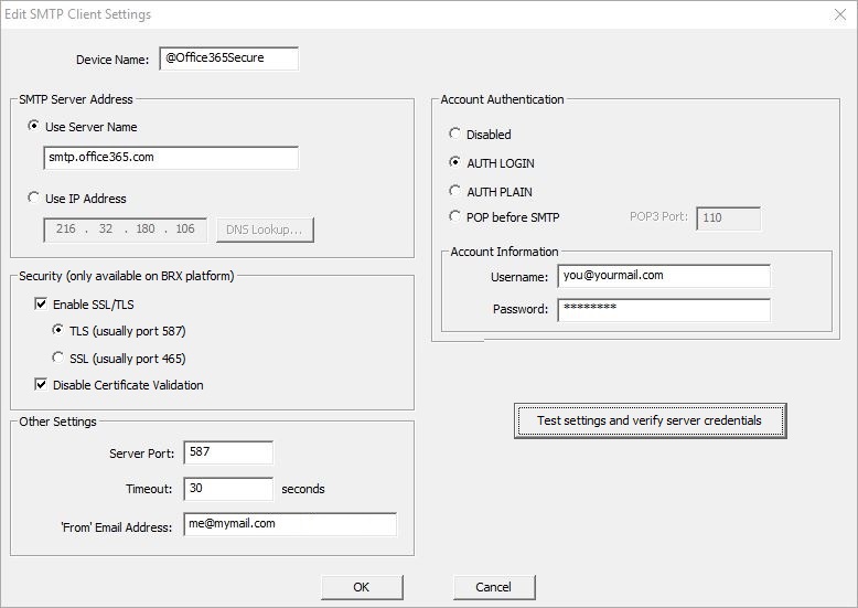
SMTP Client Device
The Add / Edit SMTP Client Settings dialog is used to create the required connection from the Do-more CPU to an SMTP server which will allow the CPU to send Email. The information required to configure any SMTP Client connection is always going to be specific to the installation. It is up to the programmer to locate the required information. The Send Email (EMAIL) instruction will use this SMTP Client to send Email.
Device Name is the name given to
the SMTP Client that will be referenced in Send
Email (EMAIL) instructions. Device Names can consists of 1 to 16 alphanumeric
characters and must follow Nickname Rules![]() Nicknames can be 1 to 16 characters in length and consist of any combination of alphanumeric characters and underscores ('_', 'a-z', 'A-Z', 0-9), no spaces or punctuation marks are allowed, and must begin with a letter or an underscore..
Nicknames can be 1 to 16 characters in length and consist of any combination of alphanumeric characters and underscores ('_', 'a-z', 'A-Z', 0-9), no spaces or punctuation marks are allowed, and must begin with a letter or an underscore..
Note: the Email instruction in Do-more Technology v2.2 and later can perform a DNS name resolution internally, that is, they can use the DNS protocol to resolve a name of an SMTP server to its IP address when the Email instruction is executed . This also means the SMTP Client can be configured to establish an encrypted connections to Email servers and optionally require trust certificate validation. The EMail instruction in Do-more Technology versions previous to v2.2 do not have this internal DNS capability. This means the SMTP Client must contain the IP address of the SMTP server, not the name of the SMTP server.
SMTP Server Address selects how the connection to the SMTP server will be established.
Select Use Server Name to enter a text string that will be resolved when the EMail instruction is executed. This selection is required if an TLS or SSL encryption to a secure Email server is selected. The CPU will use the DNS server in the Ethernet Settings configuration to resolve the server name entered.
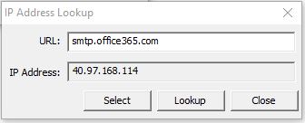
Select Use IP Address to enter the static IP address of the SMTP server. Clicking the DNS Loopkup button will open the IP Address Lookup utility in Do-more Designer that can search for the IP Address assigned to a given SMTP Server name. This requires a functional connection to a DNS Server. Enter the URL for the SMTP server then click the Lookup button. If the operation is successful click the Select button to use the IP address that was found.
Note: in Do-more Technology versions previous to v2.2, the IP Address of the SMTP Server can be resolved at runtime by using additional ladder logic instructions, specifically the Name to IP Address (DNSLOOKUP) instruction can be used to find the IP Address associated with a Server's name, then the Write Device Register (DEVWRITE) instruction can be used to set the SMTP Client Device to use the IP Address that was found. Refer to the example program in the Send Email (EMAIL) instruction to see how this is done.
Security (only available on BRX platform) options are used when establishing an encrypted connection to a secure SMTP server instead of a plain-text connection to an unsecured Port 25 server.
Note: using SSL / TLS encryption is a very CPU intensive operation because of the math involved. Because the CPU must keep the PLC's scan time in check, the SSL encoding is processed as a time-slicing event, meaning that only a portion of each scan time is used to work on the encryption; this prevents the scan time from exceeding the watchdog timer. Processing the encryption can take several seconds depending on the number of security certificates that must be processed and the amount of data being transferred.
The amount of time the CPU allots to processing TLS transactions on each scan is called the TLS Timeslice. This value can be changed on the CPU page of the System Configuration. Increasing this value can allow the TLS process to complete sooner, but at the cost of increasing the PLC's scan time. The Default TLS Timeslice value will be used by the TLS encryption engine each time the PLC powers up and goes into RUN mode. RUN-mode changes to this value can be made by changing the value in $TLSTimeslice (DST68).
Enable SSL / TLS to use an encrypted connection to the SMTP Server. Disabling this option will set the Server Port number to 25. TLS version 1.2 is currently being used.
- TLS (usually port 587) will establish an encrypted connection to the SMTP Server Address using STARTTLS protocol.
- SSL (usually port 465) will establish an encrypted connection to the SMTP Server Address using SSL protocol.
Disable Certificate Validation : if this option is NOT selected, when Do-more Designer creates the SMTP Client, it will retrieve the security certificate for the specified SMTP server from the PC running Do-more Designer, and will attach that certificate to the SMTP Client device when it is downloaded to the CPU. Each time an EMail instruction uses the SMTP Client device, the certificate is validated as part of establishing the encrypted connection. Checking the Disable Certificate Validation option will prevent the SMTP Client device from attempting to validate the certificate as part establishing the encrypted connection.
Other Settings
Server Port is the IP Port number to use when creating the connection to the SMTP server:
25 is the standard Server Port number used by plain-text (unencrypted) SMTP servers.
587 is the standard Server Port number for encrypted connections using STARTTLS protocol.
465 is the standard Server Port number used for encrypted connections using SSL protocol.
The Server Port number can be read at runtime with the Read Device Register (DEVREAD) instruction, and changed at runtime through the Write Device Register (DEVWRITE) instruction.
Timeout is the amount of time (in seconds) the SMTP Client will attempt to connect to the specified SMTP server before reporting an error. The default value of 30 seconds should be sufficient in most instances. Be aware that it is quite normal for communications with SMTP servers to take several seconds of time - especially so when using SLS / TLS encryption. Setting this value too low will only cause needless problems.
From Email Address specifies the Email address that all Emails using this SMTP Client will use in the 'From' field. Email addresses must be in the form of X@Y.Z. SMTP servers typically require that the 'From' address be configured as a recipient address on that SMTP server before they will accept Emails from that address.
Authentication is used if the SMTP server requires authentication before it will accept an Email from the Do-more CPU, select one of the following methods:
-
Select Disabled if the SMTP server does not require authentication.
-
Select AUTH LOGIN to have the client authenticate by logging into the SMTP Server with the Username and Password specified below.
-
Select AUTH PLAIN to have the client authenticate by logging into the SMTP Server with the Username and Password specified below.
-
Select POP before SMTP to use an older authentication method that attempts to get Email before attempting to send an Email, the premise being that if an Email client can log in and read Email the Client must be legitimate. Pop3 Port : the default port number of 110 is the standard IP port number for POP3 requests and should not need to be change. The Pop3 Port number can be examined at runtime with the Read Device Register (DEVREAD) instruction, and changed at runtime through the Write Device Register (DEVWRITE) instruction.
Account Information is used for authentication methods require a UserID and Password. For 'AUTH LOGIN' and 'AUTH PLAIN', the account information is for the SMTP account, for the 'POP before SMTP' method, the account information is for the POP3 account.
Username - 1 to 64 characters.
Password - 1 to 63 characters (Do-more versions previous to 2.10 only allowed 1 to 19 character passwords).
Clicking the Test settings and verify server credentials button will attempt to establish a connection to the specified SMTP Server using the options and parameters that have been selected. This step is required if the SMTP Client will use Certificate Validation.
This verification work is done by Do-more Designer - not the PLC - but it will mimic the work the PLC will do when it attempts to send Email using this SMTP Client. The Help text for the Send Email (EMAIL) instruction has a section detailing how to use Do-More Logger to debug SMTP connection issues from the PLC's perspective.
TCP Client Device
Defines a client-side TCP socket for general purpose TCP/IP networking, which is useful in cases where the Do-more CPU needs to send or receive data through a custom streaming protocol. TCP Client devices are only available if the Do-more CPU has an on-board Ethernet port. TCP Client devices require no configuration, they can create connections to TCP Server devices, but cannot accept connections from other TCP clients. Connections to TCP Servers are created through the Open TCP Connection (OPENTCP) instruction.
The TCP Client device is NOT the correct choice for connecting to servers that are using Modbus/TCP protocol, those clients should be using the Modbus/TCP Client device as described above.
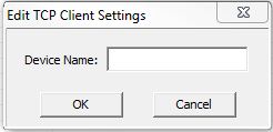
Device Name is the name to give the TCP Client. This is the name that will be referenced in the OPENTCP
instruction. Device Names can consists of 1 to 16 alphanumeric characters and must follow
Nickname Rules![]() Nicknames can be 1 to 16 characters in length and consist of any combination of alphanumeric characters and underscores ('_', 'a-z', 'A-Z', 0-9), no spaces or punctuation marks are allowed, and must begin with a letter or an underscore..
Nicknames can be 1 to 16 characters in length and consist of any combination of alphanumeric characters and underscores ('_', 'a-z', 'A-Z', 0-9), no spaces or punctuation marks are allowed, and must begin with a letter or an underscore..
TCP Server Device
Defines a server-side TCP socket for general purpose TCP/IP networking, which is useful in cases where the Do-more CPU needs to send or receive data through a custom streaming protocol. The TCP Server Device creates the required device driver that is used by the TCPLISTEN - Start Listening on TCP Port instruction.
TCP Server devices are only available if the Do-more CPU has an on-board Ethernet port. TCP Server devices are configured with a local port number, which defines the 'listening' port. TCP Server devices can accept connections from a single TCP Client, and upon accepting the client connection, will invoke a Program code-block specified for the 'connected' state, and a different Program code-block when the TCP connection is lost.
The TCP Server device is NOT the correct choice for allowing connections from devices that are using Modbus/TCP protocol, those clients should be connecting to the built-n Modbus/TCP Server .
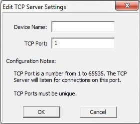
The Device Name specified here will be in the list of Devices that can be selected in the TCPLISTEN
instructions. Device Names can consists of 1 to 16 alphanumeric
characters and must follow Nickname Rules![]() Nicknames can be 1 to 16 characters in length and consist of any combination of alphanumeric characters and underscores ('_', 'a-z', 'A-Z', 0-9), no spaces or punctuation marks are allowed, and must begin with a letter or an underscore..
Nicknames can be 1 to 16 characters in length and consist of any combination of alphanumeric characters and underscores ('_', 'a-z', 'A-Z', 0-9), no spaces or punctuation marks are allowed, and must begin with a letter or an underscore..
TCP Port is the TCP port number to list on. This can be any decimal constant in the range of 1 to 65535 except port number 28784 which is already used by the Do-more CPU.
UDP Connection Device
The UDP Connection Device creates a UDP socket for general purpose Ethernet networking, useful in cases where the CPU needs to send or receive data through a custom packet-style protocol. UDP Connections are used by the Input Data from Packet Device (PACKETIN) and Output UDP to Packet Device (PACKETOUT) instructions. UDP Connections can only be created on Do-more CPUs which have an on-board Ethernet port.
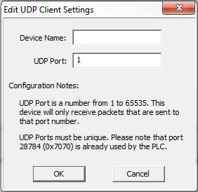
The Device Name specified here will be in the list of Devices that can be selected in the PACKETIN and PACKETOUT instructions. Device Names can consists of 1 to 16 alphanumeric
characters and must follow Nickname Rules![]() Nicknames can be 1 to 16 characters in length and consist of any combination of alphanumeric characters and underscores ('_', 'a-z', 'A-Z', 0-9), no spaces or punctuation marks are allowed, and must begin with a letter or an underscore..
Nicknames can be 1 to 16 characters in length and consist of any combination of alphanumeric characters and underscores ('_', 'a-z', 'A-Z', 0-9), no spaces or punctuation marks are allowed, and must begin with a letter or an underscore..
UDP Port : this UDP Connection will "listen" for UDP packets that the Do-more CPU receives that have this port number. This can be any decimal constant in the range of 1 to 65535 except for port number 28784 (0x7070) which is already used by the Do-more CPU. Each UDP Connection must have a unique port number.
Do-more EtherNet Peer-to-Peer Client
The Do-more Ethernet Peer-to-Peer Device creates the required device driver that is used by the Do-more Network Read (RX) and Do-more Network Write (WX) instructions.
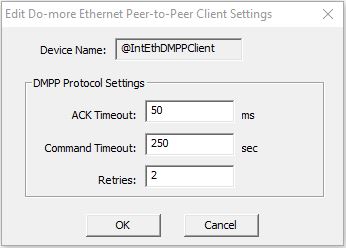
The Device Name shown here will be in the list of Devices that can be selected in the RX and WX instructions. This name cannot be changed.
DMPP Protocol Settings
ACK Timeout is how many milliseconds should the instruction wait for an ACK from the remote Do-more PLC, this can be any constant from 0 to 32767.
Command Timeout are how many milliseconds should the instruction wait for the remote Do-more PLC to respond to a data request, this can be any constant from 0 to 32767.
Retries are how many times should the instruction retry the communication with the remote Do-more PLC, this can be any constant from 0 to 255.
EtherNet/IP Explicit Message Client
The EtherNet/IP Explicit Message Client creates the required device driver that is used by the Send EtherNet/IP Message (EIPMSG) instruction.
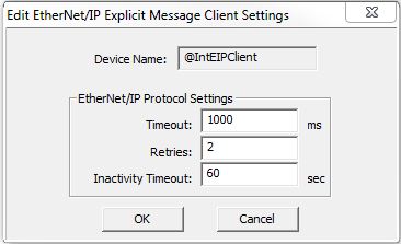
The Device Name shown here will be in the list of Devices that can be selected in the EtherNet/IP Explicit Message Client. This name cannot be changed.
EtherNet/IP Protocol Settings
Timeout is how many milliseconds should the instruction wait for the EtherNet/IP Server to respond, this can be any constant from 0 to 32767.
Retries are how many times should the instruction retry the communication with the EtherNet/IP Server, this can be any constant from 0 to 255.
Inactivity Timeout is how many seconds after the last communication from the EtherNet/IP Server to wait before the controller terminates the connection, this can be any constant from 15 to 3600.
FTP Client Device
The FTP Client creates the required device driver that is used by the Retrieve File From Remote (FTPGET) and Send File To Remote (FTPPUT) instructions.
Note: remember the Network Message Viewer (Do-more Logger) utility is a great tool to help diagnose FTP Client connection problems.
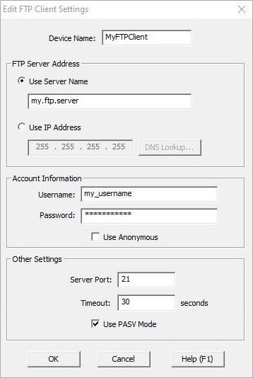
The Device Name specified here will be in the list of Devices that can be selected in the FTPGET and FTPPUT instructions. Device Names can consists of 1 to 16 alphanumeric
characters and must follow Nickname Rules![]() Nicknames can be 1 to 16 characters in length and consist of any combination of alphanumeric characters and underscores ('_', 'a-z', 'A-Z', 0-9), no spaces or punctuation marks are allowed, and must begin with a letter or an underscore..
Nicknames can be 1 to 16 characters in length and consist of any combination of alphanumeric characters and underscores ('_', 'a-z', 'A-Z', 0-9), no spaces or punctuation marks are allowed, and must begin with a letter or an underscore..
FTP Server Address selects how the connection to the FTP server will be established:
Select Use Server Name to enter a text string that will be resolved when the FTPGET or FTPPUT instruction is executed. The CPU will use the DNS server specified in the Ethernet Settings configuration to resolve the server name entered.
Select Use IP Address to enter the static IP address of the FTP server.
Account Information : a connection to an FTP server can require either a Username and Password, or the server will allow an anonymous login:
Username can be 1 to 128 characters. Password can be 1 to 256 characters. Selecting Use Anonymous will not send a User ID or Password during the login phase.
Other Settings
Server Port is the Port number to use when creating the connection to the FTP server:
21 is the standard Server Port number used by FTP most servers. Note: the Server Port number can be read at runtime with the Read Device Register (DEVREAD) instruction, and changed at runtime through the Write Device Register (DEVWRITE) instruction.
Timeout is the amount of time (in seconds) the FTP Client will attempt to connect to the specified FTP server before reporting an error. The default value of 30 seconds should be sufficient in most instances. Be aware that it is quite normal for communications with FTP servers to take several seconds of time - especially so when using SSL / TLS encryption. Setting this value too low will only cause needless problems.
Use PASV Mode determines the operational mode of this FTP client. The proper mode (PASSIVEor ACTIVE) for the FTP Client to use is determined as follows:
If the BRX CPU is separated from the FTP Server by an Internet Gateway then enabling Use PASV Mode will likely need to be required.
If the BRX CPU and the FTP Server are on the same local subnet then ACTIVE mode will probably work.
See Also:
Device Configuration
Related Topics:
DEVREAD - Read Device Register
DEVWRITE - Write Device Register