Topic: DMD0497

Pluggable Option Module (POM) Configuration
All of the BRX CPUs contain one slot where one of the POM (Pluggable Option Module) devices can be installed to accommodate an additional communication port.
Note: POMs cannot be used in the POM slot of a BX-DMIO-M (Do-more Expansion I/O Controller), BX-EBC100-M (Expansion Base Controller), or BX-MBIO-M (Modbus I/O Controller).
Note: the BX-P-ECOMEX is only a secondary Ethernet adapter, so it cannot be used with a BX-DM1-xxx CPU which does not have a Primary Ethernet adapter.
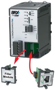
All of the POMs are hot-swappable, meaning they can be installed or removed while the BRX PLC is powered up.
Serial Communication POMs
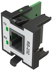
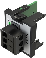
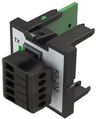
There are five Serial Communication POMs that provide connections for external serial devices. They vary by the connector type and the signal interface.
|
|
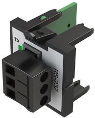
RS-232 with a 3-position terminal block
|
RS-485 with a 3-position terminal block (with termination resistor switch)
|
|
|
BX-P-SER2-TERMFC
RS-232 with hardware flow control using a 5-position terminal block
|
BX-P-SER422-TERM
RS-422 using a 5-position terminal block
|
|

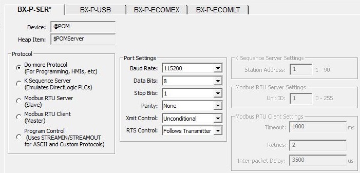
Device is the Device name that will be used in instructions that interact with this POM. All of the serial communication POMs use the same @POM device name. Heap Item is the name of the associated heap item that contains member fields that can be used in the ladder logic to interact with the POM. The heap item used depends on the protocol selection as follows:
The Do-more Protocol / K-Sequence Server / Modbus RTU Server server protocols use the $POMServer structure.
The Modbus RTU Client client protocol selection does not use a POM structure.
The Program Control selection makes the POM available for use by the STREAMIN & STREAMOUT instructions, both of which use the $POMStream structure.
Protocol options select which of the following serial communication protocols for the serial POM to use. These are the same selections that are available on the on-board serial port.
- Do-more Protocol ( for Programming, HMIs, etc.)
- K Sequence Server ( Emulates DirectLOGIC PLCs)
- Modbus RTU Server ( Slave)
- Modbus RTU Client (Master)
- Program Control (Uses STREAMIN / STREAMOUT for ASCII and Custom Protocols)
Port Settings option specify the serial POM's hardware communication parameters.
Baud Rate : 115200, 57600, 38400, 19200, 9600, 4800, 2400, 1200
Data Bits : 7, 8
Transmit Control (if applicable) specifies when data will be transmitted:
Unconditional means the data will be transmitted as soon as it reaches the output buffer.
Wait for CTS means the data will be transmitted when the CTS line is asserted.
Delayed 5ms, Delayed 50ms, Delayed 250ms, Delayed 500ms means that after data reaches the output buffer, the RTS line will be asserted, and the transmitting of the data will be delayed by the selected number of milliseconds.
RTS Control (if applicable) selects how the RTS line will operate:
If the POM is configured as a K Sequence Server, the K Sequence Server Settings are used when this Device responds to K-Sequence Client requests:
Station is the ID of the K-Sequence Server Device, this can be any constant from 1 to 90.
If the POM is configured as a Modbus RTU Server, the Modbus RTU Server Settings are used when this Device responds to Modbus/RTU Client requests:
Unit ID is the Unit ID of the Modbus/RTU Server Device, this can be any constant from 0 to 255.
If the POM is configured as a Modbus RTU Client, the Modbus RTU Client Settings are used when this Device is used in a Modbus Network Read (MRX) or Modbus Network Write (MWX) instruction:
Timeout is the amount of time (in milliseconds) the instruction should wait for the remote Modbus RTU Server to respond, this can be any constant from 0 to 32767.
Retries is the number of times the instruction should retry the communication with the remote Modbus RTU Server, this can be any constant from 0 to 255.
Inter-packet Delay is the amount of time (in microseconds) that will be placed between the Modbus RTU packets as they are sent. This can be any be any constant between 0 and 65535. The inter-packet delay creates the required "dead time" on the wire that Modbus uses to frame a packet. The Modbus specification requires this value to be a minimum of 3.5 characters times (based on baud rate). If the value entered is smaller than the required time, the Modbus RTU Client will use the minimum required time instead of the value that is entered. If the value entered is larger than the required time, the value entered will be used.
Use this formula to calculate the inter-packet delay (in microseconds) based on baud rate:
( 3.5 * (number of bits in a character / baud rate) ) * 1,000,000
For example: using a 10-bit character (1 start bit, 8 data bits, no parity bit, and 1 stop bit) at 19200 baud:
( 3.5 ( 10 / 19200 ) ) * 1,000,000 = 1823 microseconds
USB POM
The USB POM provides a port that can only be used with Do-more Designer for programming, debugging, and monitoring. This POM supports USB v1.0, v1.1, and v2.0.
|
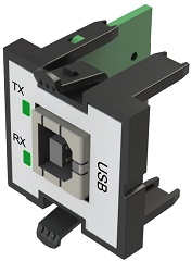
USB-B socket |
|
BX-P-USB
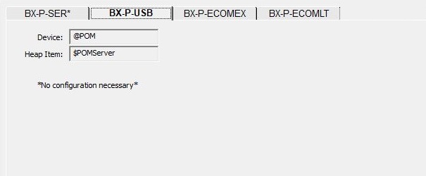
Device is the Device name that will be used in instructions that interact with this POM. All of the communication POMs use the same @POM device name. Heap Item is the name of the associated heap item that contains member fields that can be used in the ladder logic to interact with the POM.
Ethernet Communication POMs
There are two Ethernet-capable POMs which are used to add different types of network connectivity to a BRX CPU:

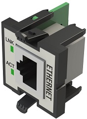
BX-P-ECOMEX
The BX-P-ECOMEX![]() is a secondary Ethernet port for BRX CPUs that already have an on-board Ethernet port. is a secondary Ethernet port for BRX CPUs that already have an on-board Ethernet port (BX-DM1E-xxx). Because it is only a secondary Ethernet port, the CPU's TCP stack will automatically route the Ethernet packets through the proper Ethernet port based on the destination IP address. This routing operation can only work properly when the ECOMEX is configured with an IP setup that places it on a different subnet than the on-board Ethernet port. This is analogous to having a second NIC in a PC which also requires that each of the PC's NICs be configured for different subnets. For example, one port configured to use 10.1.1.0 / 255.255.255.0 and the other configured to use 192.168.1.0 / 255.255.255.0.
is a secondary Ethernet port for BRX CPUs that already have an on-board Ethernet port. is a secondary Ethernet port for BRX CPUs that already have an on-board Ethernet port (BX-DM1E-xxx). Because it is only a secondary Ethernet port, the CPU's TCP stack will automatically route the Ethernet packets through the proper Ethernet port based on the destination IP address. This routing operation can only work properly when the ECOMEX is configured with an IP setup that places it on a different subnet than the on-board Ethernet port. This is analogous to having a second NIC in a PC which also requires that each of the PC's NICs be configured for different subnets. For example, one port configured to use 10.1.1.0 / 255.255.255.0 and the other configured to use 192.168.1.0 / 255.255.255.0.
Any PLC function (e.g. Ethernet I/O Master, TimeSync, Modbus I/O Scanner, etc.) or any PLC instruction (e.g. EMAIL, EIPMSG, MRX, MQTTSUB, etc.), that can use the on-board Ethernet port can use the ECOMEX as well. This allows segmenting the TCP/IP traffic into two independent domains. The CPU will automatically route the Ethernet packets for the different functions and instructions to the correct Ethernet port based on the target subnet.
Note: the ECOMEX is only a secondary Ethernet port meaning it will only work in a BRX CPU that already has a primary (on-board) Ethernet port (BX-DM1E); it does not work in BX-DM1-xxx CPUs.
Note: adding an ECOMEX to a BRX CPU will not increase the network speed of the system. The CPU has a single TCP/IP stack with its set of operating system instructions that manage the Ethernet packets flowing into and out of the Ethernet adapters. Since both adapters use the same TCP/IP stack, the BRX CPU's network throughput is ultimately limited by the CPU's scan time and the TCP/IP stack's ability to process packets, not the number of Ethernet adapters in the system.
Note: as stated earlier, the ECOMEX is only a secondary Ethernet port and shares the same TCP/IP stack used by the on-board Ethernet port. Only one of these two ports should be configured to have a Gateway address; the Gateway address of the other port should remain at 0.0.0.0. This effectively makes the port with the Gateway address a WAN port (for use with EMAIL, FTP, HTTP, etc.), and the other only a LAN port (for local traffic like Ethernet Remote I/O, or Modbus/TCP, etc.). Additionally, if the IP address configuration is being obtained automatically (by a DHCP server) make sure the DHCP setup conforms to this 'only one of the ports can have a Gateway address' rule.
There is only instance where a selection must be made between the Ethernet ports, that is when an instruction uses network broadcasts. To manage this, a Network Adapter parameter has been added to the DLRX, DLWX, PACKETOUT, PEERLINK , and PING instructions:
Default means the TCP stack will route the packets to the first Ethernet port that can process the packet; on CPUs without a Secondary port (BX-P-ECOMEX) installed, this will always be the on-board port. This is also the proper selection for backwards compatibility with previous Do-more Technology versions and with H2-DM1E, T1H-DM1E, and BX-DM1 CPUs because they have no provision for a Secondary Ethernet port.
Primary (Internal Ethernet) will send packets through the on-board Ethernet port of the Do-more CPU.
Secondary (BRX ECOMEX) will send packets through the BRX CPU's secondary Ethernet port (BX-P-ECOMEX).
The TCP/IP address configuration for the BX-P-ECOMEX can only be setup through these selections in the System Configuration; this setup cannot be done through NetEdit.
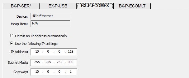
Device is the name of the Device assigned to the port. Because this is a secondary Ethernet port, the Device will be the same as the primary (on-board) Ethernet port, that is @IntEthernet. The Heap Item is empty because there is no associated heap item.
-
Select Obtain an IP address automatically to have the BX-P-ECOMEX obtains its IP Address, Subnet Mask and Gateway Address from a DHCP server each time the POM is installed in a POM slot or the CPU is powered on. Once a DHCP server assigns an address to an ECOMEX, the BRX CPU will try to get the DHCP server to assign the same IP Address information to the ECOMEX any time it returns to the network.
-
Selecting Use the Following IP settings will assign a static TCP/IP address using the following information:
IP Address can be any valid TCP/IP Address. The IP Address entered must be unique on the network where the PLC will be connected.
Subnet Mask can be any valid TCP/IP Subnet Mask.
Gateway can be any valid TCP/IP address of a network Gateway.
Note: when a BX-P-ECOMEX is installed in the POM slot, its current IP Address is stored in $Eth2IpAddress (DST62), its current Subnet Mask in $Eth2Netmask (DST63), and its current Gateway Address in $Eth2Gateway (DST64).
BX-P-ECOMLT
The BX-P-ECOMLT Ethernet POM provides an Ethernet port for use as a server to external network clients, such as the Do-more Designer programming software, C-More HMI panels, Modbus/TCP clients, etc. The BX-P-ECOMLT can be used with either BRX CPUs that have an existing on-board Ethernet port (BX-DM1E-xxx), or BRX CPUs that do not have an on-board Ethernet port (BX-DM1-xxx).
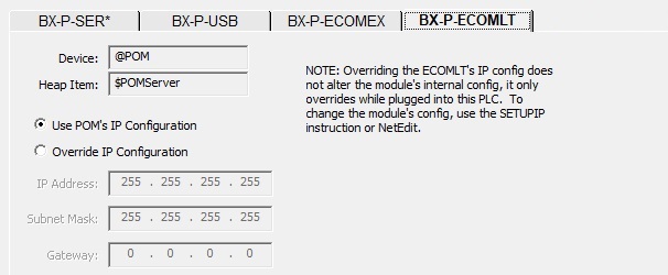
Device is the Device name that will be used in instructions that interact with this POM. Heap Item is the name of the associated heap item that contains member fields that can be used in the ladder logic to interact with the POM.
-
Selecting Use POM's IP Configuration will use the TCP/IP configuration that is stored in the BX-P-ECOMLT itself.
-
Selecting Override IP Configuration will use the TCP/IP address configuration below. Using this option does not overwrite the configuration stored in the POM itself.
IP Address can be any valid TCP/IP Address. The IP Address entered must be unique on the network where the PLC will be connected.
Subnet Mask can be any valid TCP/IP Subnet Mask.
Gateway can be any valid TCP/IP address of a network Gateway.
Note: when a BX-P-ECOMLT is installed in the POM slot, its current IP Address is stored in $Eth2IpAddress (DST62), its current Subnet Mask in $Eth2Netmask (DST63), and its current Gateway Address in $Eth2Gateway (DST64).
See Also:
POM Configuration
EtherNet/IP Server / Adapter Configuration
Ethernet I/O Master Configuration