Topic: DMD0252

Module Configuration
Some of the I/O modules need to be preconfigured before they can be used in a Do-more Designer project. For example: a CTRIO (High Speed Counter / Pulse Output) module must be configured within the System Configuration. Some Analog I/O modules need their input range, output range, and / or resolution to be set at system startup. Some Analog I/O modules have configuration options that can be changed at runtime but need to be initialized. Modules with Serial ports must have those ports configured so the necessary resources can be allocated.
A module configuration consists of a Name that is used by instructions that can target the I/O module, a Type that defines the type of module configuration that is required to access the module, and a Location that specifies the base and slot where the module physically resides in the I/O system. The module's configuration creates a logical connection between the Do-more Designer project and the I/O module, thereby eliminating the need to use the physical Base & Slot addressing in the project.
When a Do-more CPU first detects an I/O module that requires
a module configuration it will automatically create one and set default
values for each of its fields. The default name for these configurations
will be in the form <Module Type>_<Master><Base Number><Slot
Number>. For example: A CTRIO module in the local base, slot #2 will have
a default configuration named CTRIO_002. An F2-8AD4DA-2 analog module in the local base, slot
#7 will have a default configuration name of F2_8AD4DA_007. A Terminator I/O Analog output module in Base #1, slot
#5, that is managed by the Ethernet I/O Master will have a default configuration
named TERMAO_115. An H2-SERIO-4 installed as the first I/O Module will have a default configuration name of SERIO_001.
A module' configurations is written to it by the CPU any time a base initialization operation is performed. This happens when the PLC is powered up, any time an update to the System Configuration is written to the CPU, or any time a Re-initialize PLC I/O operation is performed.
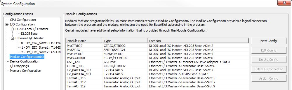
The Module Name column displays the logical name assigned to the I/O module, the Type column displays the type of I/O module configuration used for the module in that Location, and the Location column displays the I/O Master, the Base and the Slot number of the I/O module. If a module configuration exists for a module that is not currently detected in the base, the Location field for that entry will change to Disconnected.
Because the different I/O modules have different configuration needs, there is a type-specific editor for each I/O module. New Config and Edit Config will open a type-specific editor to change the configuration of the highlighted entry. Delete Config will remove the highlighted module configuration. Delete Disconnected and Assign Config are used to manage module configurations that are no longer connected to an actual module. Refer to the Handling Unassigned Module Configurations section below for more details on how these operations work.
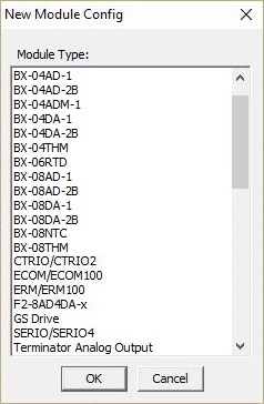
Creating and Editing Module Configurations:
When a Do-more CPU powers up and detects a new I/O module, or when the Ethernet I/O Master configuration adds a new I/O module to an Ethernet I/O Slave, a module configuration for that new module will automatically be created if it needs one.
|
|
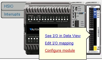
You can also get to the module's configuration dialog from the Dashboard by clicking on the module and selecting Configure module as shown to the left: |
Handling Disconnected Module Configurations:
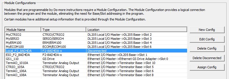
When a Do-more CPU is powered up it cycles through each of the module configurations in the current System Configuration. For each module configuration found, it checks to see if the correct I/O module is still installed in the correct I/O Master -> Base -> Slot location. Any module configuration where the I/O module is missing or is not the correct module type for that configuration is marked as Disconnected. This situation where this is most likely to happen is when an I/O module the requires a module configuration is removed from the base. The module configuration itself is retained so that, if needed, can be assigned to a replacement module or to a module of the same type in a different Master -> Base -> Location.
Note: the "Module configuration changed at power up (ST134)" Info message will be generated and displayed in the System Information dialog, and 'Info' will be displayed on the Status Bar.
The screen capture shows a disconnected CTRIO module configuration.
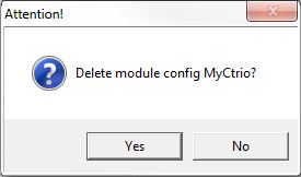
Delete Config will remove the highlighted module configuration. Highlight the configuration in the list and click the Delete button, confirm the delete operation on the subsequent dialog.
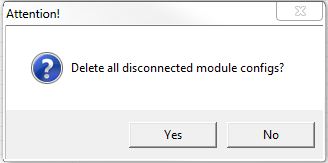
Delete Disconnected will remove all of the Disconnected module configurations, confirm the delete all operation on the subsequent dialog.
Assign Config is used to reconnect a Disconnected module configuration to an I/O module in a designated location. Highlight the disconnected configuration in the list and click the Assign Config button. The Assign Module Config dialog will display a list of the I/O modules that can be assigned to the selected Module configuration. Highlight the I/O module in the list to use.
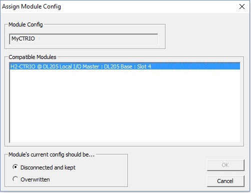
The Module's current config should be ... option specifies what to do with the module configuration of the target I/O module.
-
Disconnected and Kept means the target I/O module's existing module configuration data will be saved and marked as Disconnected before the new module configuration is assigned to this IO module.
-
Overwritten means the target I/O module's module configuration will be overwritten when the new module configuration is assigned to this I/O Module.
Click OK to Assign the selected I/O module to the Module Configuration, then click Yes on the subsequent confirmation dialog to complete the operation.
Click Cancel to leave the current module configuration intact.
See Also:
Module Configuration