Topic: DMD0265

Network Configuration
The on-board Ethernet port of a Do-more CPU supports only the TCP/IP protocol. Before any TCP/IP client - for example Do-more Designer, C-More panel, etc. - can connect to this port it must first be configured to operate on the same TCP/IP network as the client that wants to connect. This initial network configuration requires a minimum of an IP Address and Subnet Mask.
A copy of the current values for the IP configuration are stored in the $IPAddress (DST18), $NetMask (DST19), and $Gateway Address (DST20). They are best viewed in a Data View using the IP Address display format). Any time the IP configuration changes the values in these locations is updated with the new values.
Using NetEdit to Configure the Network Settings for the On-board Ethernet Port
The typical way to initially configure the network settings for the on-board Ethernet port is with NetEdit 3 (version 3.81 or later). This utility is installed as part of Do-more Designer; there is a link to it in the Applications section of the Launchpad. Double click that link to start the utility which will begin by scanning the local network for Do-more CPUs and will then list any of the CPUs that were found in the center portion of the dialog similar to the following :
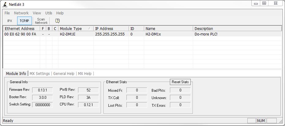
Changing the TCP/IP Network Settings
Right-click the entry for the CPU then select General... from the pop-up menu to open the General Settings dialog where the TCP/IP settings can be changed.
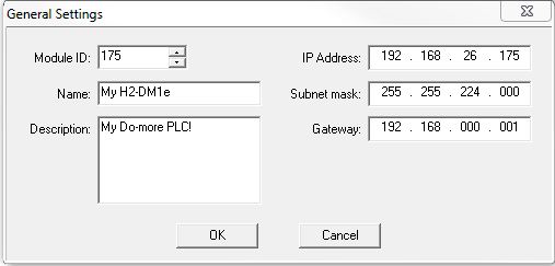
Module ID: - the Module ID can be any positive 32-bit signed number from 0 to 2147483647.
Name: - the Name can consist of 0 to 256 characters.
Description: - the Description can consist of 0 to 256 characters.
IP Address: - the IP Address
is entered as 4 separate decimal numbers, each one ranging from 0 to 255.
IP Addresses 0.0.0.0, 127.0.0.1, and 255.255.255.255 are not allowed
Subnet Mask: - the Subnet Mask is entered as 4 separate decimal numbers, each one ranging from 0 to 255. Addresses 0.0.0.0, and 255.255.255.255 are not allowed.
Gateway: - the Gateway Address is entered as 4 separate decimal numbers, each one ranging from 0 to 255. Addresses 127.0.0.1 and 255.255.255.255 are not allowed. An address of 0.0.0.0 means there is no Gateway defined.
Click the OK button to write the current settings to the CPU.
Click the Cancel button to exit this dialog without writing any of the changes to the CPU.
Connect with USB or a Serial Link and Use System Information Dialog
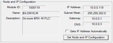
If Do-more Designer can connect to the CPU using one of it's other ports (USB, serial port, or through a POM) the network settings can also be set through the Node and IP Configuration of the System Information
dialog which displays the current Node configuration and the setup of the on-board Ethernet port (on models that have them).
Configure the Ethernet Settings with Ladder Logic Instructions
The network settings can be set through the use of two ladder logic instructions. The Setup TCP/IP Parameters (SETUPIP) instruction is used to configure the TCP/IP networking parameters, and the Setup Ethernet Node Parameters (SETUPNOD) instruction is used to configure the Node Identifying parameters for the on-board Ethernet port.
Clear the Network Configuration of On-board Ethernet Port
Do-more CPUs DO NOT support DHCP protocol for automatically obtaining the TCP/IP setup parameters from a DHCP server; the TCP/IP setup is done through fixed (static) values. As such, there will be times when the network configuration needs to be cleared (or temporarily set to some known values). For example, the CPU is moved to a network with TCP/IP settings that make it unreachable with software, or the IP Address is unknown, or the IP address was entered incorrectly which also makes the CPU unreachable.
There are four ways to accomplish this: the method chosen will largely depend on the reason the setup needs to be cleared.
Do-more Designer USB or Serial port - the preferred method for clearing or resetting the TCP/IP network parameters is to use Do-more Designer to connect to the CPU through the on-board USB port, the on-board Serial port, or through an ECOM100 module in the base, then either clear the network configuration, or set the network parameters to functional values for the local network.
NetEdit 3 -> Restore Factory Defaults - restoring the factory defaults will reset the Module ID, Name, Description, IP Address, Subnet Mask and Gateway fields to their factory default values. This method requires that NetEdit 3 be able to locate the module on the local network. Be aware that this clears more than just the TCP/IP settings.
DIP switch setting / Mode switch operation - follow this link to the topic describing a series of Mode switch manipulations with a specific DIP switch setting that will reset the network settings to their factory defaults.
SETUPIP - Setup TCP/IP Parameters - Add this instruction along with some method to externally trigger it to the project in the PLC to set the IP Address, Subnet Mask and Gateway to a set of preset values that will work on the local network. At that point NetEdit 3 should be able to find the CPU accessible, and be able to set the TCP/IP settings as required.
See Also:
System
Setup and Maintenance Overview
Configuring
the Hardware Watchdog Timer
Mode Switch Position
Definitions
Configuring the On-board Ethernet Port
Related Topics:
SETUPIP - Setup TCP/IP Parameters