Topic: DMD0250

I/O Mappings
At power-up, Do-more CPUs will automatically detect any on-board I/O and any installed I/O modules (including specialty modules) and create the correct I/O configuration and assign I/O addresses for them. For most applications, you will never have to change the I/O Mapping configuration.
I/O addresses for the discrete and analog I/O modules found are assigned in decimal, starting at X0 and Y0 for Discrete I/O and WX0 and WY0 for Analog I/O, beginning with any on-board I/O then with the module adjacent to the CPU. The addresses are assigned in increments of 8, depending on the number of points for the I/O module. Discrete and Analog I/O modules can be mixed in any order, but there may be restrictions placed on some specialty modules.
Intelligent I/O modules are not assigned discrete and / or analog mapping; they are accessed through a system-created structure, and that structure name will appear in the Slot I/O column.
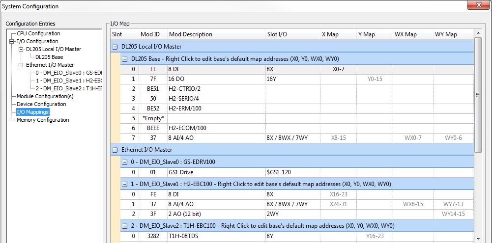
The I/O Map group displays the current mapping information for all of the I/O modules in the system, grouped by I/O Master. The image above shows the I/O mapping for a system that has 9-slot DL205 local base, the Ethernet I/O Master is enabled, and configured with three Ethernet I/O Slaves: one GS-EDRV100, one H2-EBC100, and one T1H-EBC100. The I/O Mapping information for each I/O module in each base is displayed to the right of each module.
The Slot column displays the slot number in which the module is detected.
The Mod ID column displays the Module ID of the I/O module that is detected. For DL205 and Terminator systems, I/O modules that have the same I/O footprint will also have the same Module ID regardless of the type of I/O, for example, all of the 8-point Discrete input modules will have the same Module ID, regardless of whether they have AC or DC inputs.
The Mod Description column displays a short description of the module. The different I/O systems provide varying amounts of information to the Do-more CPU; this column displays as much descriptive text as the I/O system provides, This can be as little as simply describing the I/O type and count, or as much as the actual part number. I/O modules that have multiple types of I/O will display each number and type separated by a "/":
x DI - Discrete Inputs - for example 16 DI = 16 Discrete Inputs.
x DO - Discrete Outputs - for example 8 DO = 8 Discrete Outputs.
x DI / y DO - Combo Discrete Inputs & Outputs - for example 4 DI / 4 DO = 4 Discrete Inputs & 4 Discrete Outputs.
x AI - Analog Inputs - for example 4AI = 4 Analog Inputs.
x AI (RTD / THM) - Analog Temperature Inputs - for example 4AI (RTD / THM) = 4 Analog Temperature Inputs.
x AO (12 bit) - Analog Outputs with 12 bit resolution - for example 2 AO (12 bit) = 2 Analog Outputs with 12 bit resolution.
x AO (16 bit) - Analog Outputs with 16 bit resolution - for example 2 AO (16 bit) = 2 Analog Outputs with 16 bit resolution.
x AI / y AO - Combo Analog Inputs & Outputs - for example 8 AI / 4 AO = 8 Analog Inputs & 4 Analog Outputs.
H2-CTRIO/2 - either an H2-CTRIO or an H2-CTRIO2.
T1H-CTRIO/2 - either an T1H-CTRIO or an T1H-CTRIO2.
H2-SERIO/4 - either an H2-SERIO or an H2-SERIO-4.
H2-ERM/100 - either an H2-ERM or an H2-ERM100.
H2-ECOM/100 - either an H2-ECOM or an H2-ECOM100.
Some I/O systems can provide the Complete Module Part Number for the I/O modules - for example BX-16TD1 or T1H-08TDS.
Some I/O systems can only provide a Partial Module Part Number for the I/O modules that have similar input types and sizes - for example, T1F-08ADx is reported for both the -1 and -2 variants of this module; another example, T1F-16RTD/14THM is reported for both the T1F-16RTD and the T1F-14THM modules.
*Empty* is shown if no I/O module was detected in the slot.
The Slot I/O column displays
the number and type of I/O points that the detected in a slot, The on-board I/O in BRX CPUs will be shown in Slot 0.
Modules that have multiple types of I/O will display each number and type
separated by a "/":
X - Discrete Inputs - for example 16X = 16 discrete inputs.
Y - Discrete Outputs - for example 8Y = 8 discrete outputs.
Note: 12pt. discrete I/O modules consume 16 points.
In BRX systems the 12 points are assigned to the first 12 locations, then the next 4 are skipped.
In DL205 systems, The first 6 points are assigned, two are skipped, then the next 6 points are assigned. For example, a D2-12TA installed in slot 0 would use Y0 to Y5, and Y8 toY13 for the actual inputs; Y6 to Y7 and Y14 to Y15 would be unused.
Note: 4 point discrete I/O modules consume 8 points. The first 4 points are assigned to the actual I/O points, the next 4 are unused. For example, a D2-04TD1 installed in slot 0 would use X0 to X3 for the actual inputs and X4 to X7 would be unused.
WX - Word (Analog) inputs (16-bit signed) - for example 4X / 4WX = 4 discrete inputs and 4 Word (Analog) inputs. The Discrete inputs for Analog input modules are the alarm bits, one bit per channel .
WY - Word (Analog) outputs (16-bit signed) - for example 4WY = 4 Word (Analog) outputs
A structure name (for example $GS1_120, or $MyCTRIO2) indicates there is no I/O assigned to the module; the module is accessed through the system-created structure listed in this column and instructions specifically designed for this device type. The member fields for these structures can be seen under the Memory -> I/O -> Specialty section in the Project Browser.
The X Map column displays the current I/O Address range for the Discrete Input module in that slot.
The Y Map column displays the current I/O Address range for the Discrete Output module in that slot.
The WX Map column displays the current I/O Address range for the Analog Input module in that slot.
The WY Map column displays the current I/O Address range for the Analog Output module in that slot.
How to Manually Configure the I/O Map
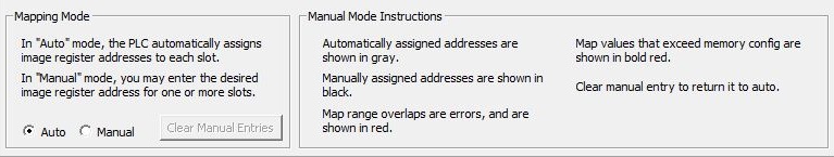
In Auto Addressing Mode (the default mode) the Do-more CPU automatically assigns I/O addresses to the on-board I/O and the modules in each slot. Automatically assigned I/O addresses are displayed in gray.
It may never become necessary, but in Manual Addressing Mode Do-more CPUs allow manual I/O address assignments for the on-board I/O and any of the I/O modules in the system. The automatic configuration can be changed to match any required I/O numbering scheme.
Click the Clear Manual Entries - (only valid in Manual Mode) button to remove any manual changes that have been applied and revert to the Automatically assigned addresses for each I/O module in the system.
The manual renumbering process begins by selecting Manual Mode. Click once on the I/O address block in the I/O Map grid that is to be changed.
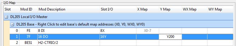
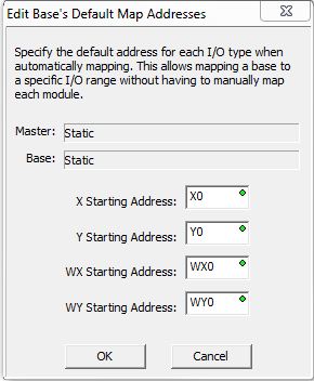
Only the beginning I/O address for a module can be specified, the range of addresses will be automatically assigned based on the number of I/O points the module consumes. Manually assigned I/O addresses will be displayed in black. To change the default mapping for the entire base, right-click on the blue header bar for the base and the following dialog will be displayed which allows the beginning address for all four of the I/O ranges to be changed:
WARNING: the Do-more CPU does not allow duplicate I/O addresses. So, if you manually configure the addresses of an I/O slot, the I/O addressing for the other modules that consume I/O addresses in the same range may change. For example, if you manually assign addresses for a discrete output module, then addresses for subsequent discrete output modules may change if there is a need to make room for the range of addresses the module requires. Any I/O configuration errors must be corrected before you can place the CPU in RUN mode. Uncorrected errors can cause unpredictable machine operation that can result in a risk of personal injury or damage to equipment.
Manually assigned addresses that create overlapping ranges will be displayed in red and must be corrected before the changes can be saved. Manually assigned addresses that result in ranges outside of the configured range of that I/O Type will be displayed in bold red and must be corrected before the changes can be saved.
See Also:
I/O Mappings