Topic: DMD0225

WX - Do-more Network Write
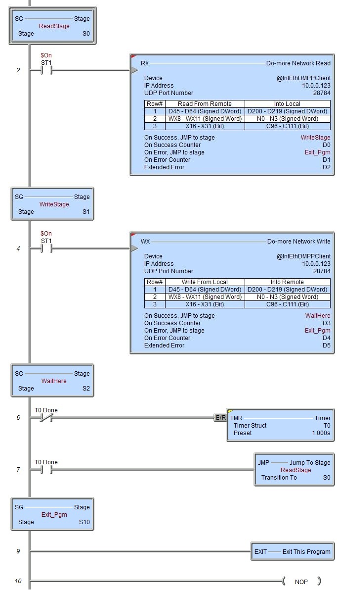
The Do-more Network Write (WX) instruction uses the Do-more proprietary protocol to write data over the on-board Ethernet port or a BX-P-ECOMEX POM to another Ethernet-equipped Do-more CPU. The WX instruction uses UDP (not TCP) protocol to communicate with the remote Do-more CPU. Do-more WX is the preferred way to write data to a remote Do-more CPU because it has direct access to nearly all of the memory in the remote CPU - including direct access to the PLC's I/O memory. This is in contrast to DirectLOGIC (DLRX / DLWX) and Modbus/TCP (MRX / MWX) network communication which only has access to the protocol-specific memory blocks in the remote CPUs. instruction
Each WX instruction can contain up to 50 individual write requests for a total of up to 1000 bytes of data. The WX instruction can write to all of the built-in memory blocks, all of the built-in structures, and any user-created memory blocks in the remoteCPU. WX does NOT support writing to a Heap Item![]() A Heap item and it's associated memory are not preallocated in a default Memory configuration. They are single items as opposed to one entry of a memory block. A Heap Item can be created in the Memory Configuration or be created when the instruction using it is added to the ladder diagram. in the remote Do-more CPU.
A Heap item and it's associated memory are not preallocated in a default Memory configuration. They are single items as opposed to one entry of a memory block. A Heap Item can be created in the Memory Configuration or be created when the instruction using it is added to the ladder diagram. in the remote Do-more CPU.
The WX instruction establishes a communication session with the remote Do-more CPU similar to Do-more Designer and C-More panels. The session is established using one of the User Accounts setup in the System Security of the remote CPU. The User Account selected will enforce any restrictions on what can be accessed by this instruction. Even if no password is selected, the session will be established using the Default User account.
This instruction uses either the on-board Ethernet port or BX-P-ECOMEX POM, both of which are shared, system resources controlled by a device driver. The device driver allows the Ethernet port to process concurrent client-side requests ( RX, WX, DLRX, DLWX, MRX, MWX, EIPMSG, EMAIL, etc. ) without the need for additional interlocking logic in the ladder program.
Element References:
Note: Use the F9 key or click the 'three dot box' at the right edge of the parameter field to open the Default Element Selection Tool (the Element Picker or the Element Browser) or use the Down-Arrow key (Auto-Complete) on any parameter field to see a complete list of the memory locations that are valid for that parameter of the instruction.
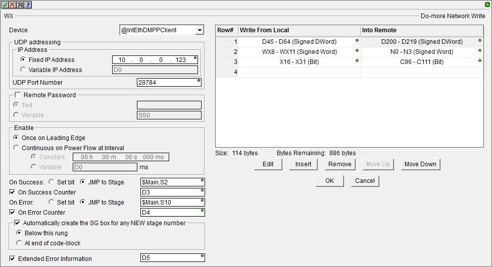
Device : the only Device that can be selected $IntEthDMPPClient.
UDP Addressing
IP Address is the IP Address of the Do-more CPU that will receive the data. This can be either a Fixed (static) IP Address or a Variable (dynamic) value.
Select Fixed Address to manually enter the TCP/IP Address assigned to the Do-more CPU in the instruction. IP addresses are canonically represented in dot-decimal notation, consisting of four decimal numbers, each ranging from 0 to 255, separated by dots.
Select Variable IP Address if the IP Address resides in the specified numeric memory location. This can be any readable DWord numeric location. The Hexadecimal equivalent of each octet of the IP Address is stored in a byte of the Variable Address location. For example: IP Address 192.168.100.006 in Hex would be C0.A8.64.06, and stored in the Variable Address location as 0xC0A86406. The 'IP Address' format selection in a Data View can be used to see the IP Address stored in the DWord location in the traditional dot-decimal notation (000.000.000.000).
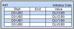
If this value will be sourced externally, like from a C-More panel, and it consists of 4 individual values, each written to a separate memory location, consider using the Initialize Data (INIT) instruction to "pack" these 4 externally sourced values into the 4 bytes of the DWord that will be used in the instruction. In the example below, the 4 octet values of the IP Address have been written to 4 successive DLV memory locations:
DLV0 = 192 (0x00C0)
DLV1 = 168 (0x00A8)
DLV2 = 100 (0x0064)
DLV3 = 006 (0x0006)
The Initialize Data instruction will extract the lower Byte (:B0) of each DLV location (using the :UB and :B cast operators) and place them into the 4 Bytes of the DWord location D0 in the proper order.
TCP Port Number is the port number of the Do-more that will receive the data. The default value of 28784 (0x7070) is typically the correct number for Do-more protocol. This can be any constant value between 0 and 65535, or any readable numeric location containing a value in that range.
Remote Password : the WX instruction requires that a communication session be established with the remote Do-more CPU before the data write operations can be processed. Depending on how the remote system is configured, this may require the user to enter the password for the User Account on the target CPU to allow the session to be established.
If no remote password is selected, the connection will be established using the Default User account. If that account exists on the remote system AND that account has Write Data privilege the connection will be made and the write data operations will be processed. If the Default User does not exist a connection cannot be established and thus the WX operation will fail. If the Default User account has been changed to NOT have Write Data privilege the write data operations cannot be processed.
If a remote password is selected, the connection will be made using the password specified below. If that account exists on the remote system AND that account has Write Data privilege the connection will be made and the write data operations will be processed. If a connection cannot be made using the specified the password the connection cannot be established and the WX operation will fail. If the account specified by the password does NOT have Write Data privilege the write data operations cannot be processed.
The password for the User Account can be supplied in either of the following ways:
Select Text to enter the password directly in the field provided. Passwords are 4 to 32 characters in length (Do-more versions previous to 2.10 only allowed 4 to 8 character passwords), with no embedded white-space characters, and are case sensitive. Leave this empty for Default User with no password.
Note: the password is obfuscated in the instruction editor, but it is it NOT encrypted when the instruction is saved. The contents of the password field will be displayed in plain text in the text file if the project is Exported, and in the Output Window in the result of a Find All operation.
Select Variable if the password already exists in a String, enter that String in the field.
Enable specifies how this instruction is enabled. Select from one of the following:
-
Select Once on Leading Edge to have this instruction run to completion exactly one time. Typically, this will take more than one scan. Configured this way the Do-more Network Write (WX) instruction is Edge Triggered
 Each time the input logic transitions from OFF to ON this instruction will execute. With each execution, this instruction will run to completion even if the input logic transitions to OFF before the instruction completes..
 -
Select Continuous on Power Flow at Interval to have this instruction run as long as the instruction has power flow. After the Do-more Network Write (WX) has initially run, if the instruction still has power flow, the instruction will remain enabled and will wait the specified amount of time before running again. The following options selects how much time (in milliseconds) to wait between successive runs.
-
Constant specifies the interval time in Hours / Minutes / Seconds / Milliseconds.
-
Variable can be any readable that contains a value between 0 and 2,147,483,647 which represents the number of milliseconds to wait before running again. A value of 0 ms means this instruction will be set to run on the next scan.
The On Success and On Error parameters specify what action to perform when this instruction completes. You do not have to use the same type of selection for both On Success and On Error.
If the Set Bit selection is used for either On Success or On Error, the specified BIT location will be SET OFF when the instruction is first enabled and will remain OFF until the instruction completes. Once complete, the appropriate Success or Error bit location ON. The specified Bit location is enabled with a SET (Latch) operation meaning that it will remain ON even if the input logic for the instruction goes OFF.
If the JMP to Stage selection is used for either On Success or On Error the target Stage must be in the same Program code-block as this instruction, you cannot specify a target Stage that exists in a different Program code-block. When the operation finishes, the target Stage will be enabled the same way as a standalone Jump to Stage (JMP) instruction would do it. The JMP to Stage option will only be available if this instruction is placed in a Program code-block.
On Success selects which of the following actions to perform if the operation is successful:
- Enable SET Bit then specify any writable bit location.
- Enable JMP to Stage then specify any
Stage number from S0 to S127 in the current Program code-block.
On Error selects which of
the following actions to perform if the operation is unsuccessful:
- Enable SET Bit then specify writable bit location.
- Enable JMP to Stage then specify any Stage number from S0 to S127 in the current Program code-block.
If either the On Success or On Error selections are set to JMP to Stage, Automatically create the SG box for any NEW stage number will be enabled which will automatically create any target stage that does not already exist.
- Below this rung will create the new target stage on a new rung following this instruction.
- At end of code-block will create the new target stage as the last rung of this Program.
Enable the On Error Counter option and specify a DWord location to store the total number of times the WX failed to complete. This can be any writable DWord location.
Enable the Extended Error Information option then enter a memory location to store any error codes returned for this instruction. This can be any writable numeric location. The following lists the Extended error responses and their meaning:
-1 = Protocol Error occurred. The value in LastProtoError (DST38) contains the protocol error code as follows:
2 (0x02)= Out Of Sessions: the remote PLC currently has 32 concurrent connections and cannot accept any more.
3 (0x03) = Illegal Operation: the User Account for the password in the instruction does not have Write Data privilege.
4 (0x04) = Invalid Session: an error occurred with the session to the remote PLC, for example the remote PLC lost power during the session.
6 (0x06) = Invalid Argument: the write requests are not formed properly (you should never see this).
14 (0x0E) = Invalid Password: the password in the instruction does not match any User Account in the remote PLC,
20 (0x14) = Bad DMPP Request: one or more of the write requests cannot be processed, most likely the request is for a location that is out of range on the remote PLC or the memory block doesn't exist on the remote PLC. The Extended Error location will contain the entry number of the write request that is causing the error.
0 = No Extended Error
1 - 50 = row number of the bad write request if the Last Protocol Error Code was 20 (0x14).
A single Do-more Network Write instruction can process up to 50 individual data requests. The total amount of data that the 50 data requests can write is 1000 bytes. Each of the individual write operations can write one data type into a memory location that is the same type and size.
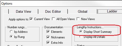
Note: if the number of individual write operations in the instruction makes the ladder display of the instruction unwieldy, you can use the View -> Options -> Display Short Summary to only show a small number of the individual write operations. This will make viewing the rungs around the WX instruction move more smoothly.
The type of data that's being written determines how many elements of each type can be written in each data request as shown below:
Bit: each data request can write a maximum of 255 Bytes of Bits. The Remote, Local and Number of Elements parameters must be on Byte boundaries.
Byte: each data request can write a maximum of 255 Bytes.
Word: each data request can write a maximum of 127 Elements (2 bytes each).
DWord: each data request can write a maximum of 255 DWords (4 bytes each).
Real: each data request can write a maximum of 255 Reals (4 bytes each).
Short String: each data request can write a maximum of 13 Short Strings (68 bytes each).
Long String: each data request can write a maximum of 3 Long Strings (260 bytes each).
Structure: each data request can write a maximum of 255 Structures (number of bytes is different for each structure).
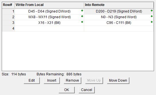
The buttons are for functions which manage the rows in the instruction: Edit opens the editor for the currently selected row, Insert adds an empty row before the currently selected row and opens the editor for this new row, Remove deletes the currently selected row from the table, and Move UP / Move Down shifts the currently selected row up one or down one row respectively in the table.
When using the Insert or Edit operations the row editor dialog will open. The Row Editor will allow you to construct write requests that will fit within the rules for the data types stated earlier.
Be aware that because the local CPU does not have access to the memory configuration of the remote system, there is no guarantee that a write request that is correctly formed on the local CPU will work when the remote system tries to execute it. For example, you could write data from a memory location that is valid locally (D4000 - D4095) but the range of D memory locations may have been adjusted in the remote CPU to stop at D3000.
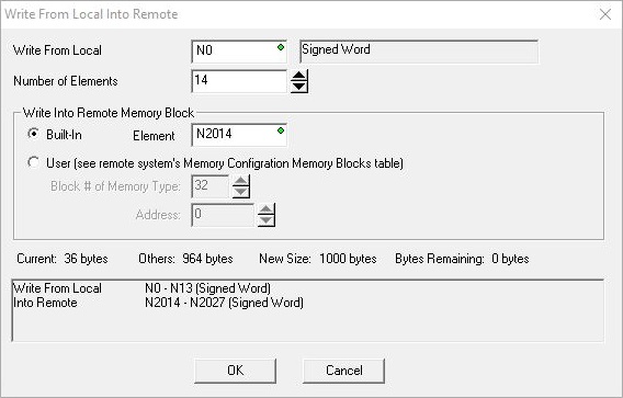
Write From Local into Remote selects the first location of the source data in the Local CPU to write to the remote CPU.
Number of Elements is the number of consecutive elements in the memory block to write.
Write into Remote Memory Block selects the beginning location in the remote CPU to store the data from the write operation. This location must be the same data type and have the same element size as the specified Write From Local data location. For example you can write from WY (Signed Word) into N (Signed Word) but you cannot write from WY (Signed Word) into V (Unsigned Word)
- select Built-In to write into one of the built-in memory blocks in the remote CPU. You will need to enter the first element in the memory block in the Element field.
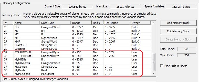
- select User to write into a memory block that was manually created (not built-in). You will need to enter the Block Number assigned to the user memory block in the remote CPU and the offset of the first element in the memory block in the Address field. When User Blocks are created they are assigned a number starting at 32. The number in the first column ( # ) is the block number that was assigned to a user memory block in the Memory Configuration page of the System Configuration as shown below:
The remaining fields are to help you maintain the size limitations of the instruction. These fields validate immediately as you make changes in the editor. Current is the number of bytes in the write request currently being edited, Others is the number of bytes in the write requests already in this instruction, New Size is the total number of bytes of all the write requests in this instruction (including the one currently being edited), and Bytes Remaining is the number of bytes of the 1000 byte limit remaining for write requests in this instruction.
OK closes the editor, saving any changes.
Cancel closes the editor, discarding any changes.
Status Display:
The red triangle in the upper left corner of the status display indicates this is a Fully Asynchronous instruction.
See Also:
WX - Do-more Network Write
Modbus Exception
Response Codes
DLRX - DirectLOGIC Network Read
DLWX - DirectLOGIC Network Write
EIPMSG - Send EtherNet/IP Message
Related Topics:
PUBLISH - Translate from Do-more
SUBSCRIB - Translate to Do-more
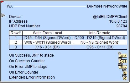
Example: