Topic: DMD0249

I/O Configuration
I/O Configuration
The Top level of the I/O Configuration dialog displays a graphical view of the I/O Bases that are currently configured.
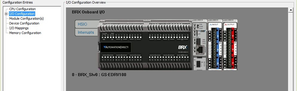
The top-most graphic will always be the base that contains the Do-more CPU and the I/O modules that are in that PLC system. Additional graphics for any Ethernet I/O Slaves will follow in the order they were added during the Ethernet I/O Master configuration.
I/O Masters
Expanding the I/O Configuration will display the list of the I/O Masters that are currently in use to interface to the local and remote I/O bases in the system.
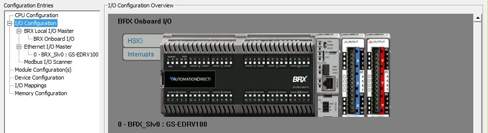
This list will contain one or more of the following depending on the PLC system in use and the CPU type in that system:
BRX Local I/O Master is the backplane driver on BRX series CPUs.
If the CPU is a Do-more Expandable BRX PLC, selecting BRX On-board I/O will expand to display the types of I/O that allow for further configuration. The configuration needs of the on-board I/O vary by part number. One or more of the following will apply:
Input Filters allow digital filtering for all on-board discrete inputs to reject false ON / OFF transitions in electrically noisy environments.
Interrupt Triggers allow BRX CPUs with the High-Speed I/O inputs to be configured to execute Interrupt Service Routines based on Input events, Timer values, and register comparisons. Interrupt Triggers can be created in the System Configuration and through the Interrupt Configuration Editor (INTCONFIG) instruction.
High-Speed I/O allow BRX CPUs with High-Speed I/O inputs to operate as high speed inputs for rotary encoders, edge timers and counters, and pulse-catch inputs, and High-Speed Outputs configured for Pulse Outputs, Preset Tables, Pulse-Width Modulated outputs, etc.
Analog Inputs and Outputs allow configuration of the range, resolution and scaling for any BRX CPUs with on-board analog Inputs and outputs.
DL205 Local I/O Master is the backplane driver for the Do-more H2 series CPUs.
DL205 Base if the CPU is an H2-DM1 or H2-DM1E in either a 3, 4, 6 or 9-slot base.
Terminator Local I/O Master is the backplane driver for the Do-more Terminator series CPUs.
Terminator Baseif the CPU is a T1H-DM1 or T1H-DM1E with up to 16 attached I/O modules.
Ethernet I/O Master will be usable on Ethernet-equipped Do-more CPUs.
The Ethernet I/O Master can use any combination of up to 16 BX-DMIO-x, BX-EBC100-x, H2-EBC100, T1H-EBC100, or GS-EDRV100 devices as Ethernet I/O Slaves - be aware that H2-EBCs, H4-EBCs, and GS-EDRVs are NOT compatible devices for use as Ethernet I/O Slaves. Detailed information on configuring the Ethernet I/O Master - including selection of the Ethernet I/O Slaves, and handling error conditions - is covered in its own help topic.
Modbus I/O Scanner will be usable on all Do-more CPUs.
The Modbus I/O Scanner allows Do-more CPUs to process Modbus Read and Modbus Write requests similarly to the way it handles local I/O and Ethernet Remote I/O. It does this by creating a Scanner Device for any combination of up to 32 Modbus/TCP or Modbus/RTU servers. The Scanner Device can additionally perform any required format conversion on the data, removing the need to add ladder logic to process the data before it is sent or after it is received. In PROGRAM mode, the Modbus I/O Scanner will process all of the Modbus Reads for all of the configured Scanner Devices, but the Modbus Writes will NOT be processed. When the CPU transitions to RUN mode, the Modbus I/O Scanner will begin processing the Modbus Writes in addition to the Modbus Reads. Detailed information on configuring the Modbus I/O Scanner is covered in its own help topic.
Note: the Modbus I/O Scanner continuously processes the Reads and Writes for the configured Scanner Devices, but there may be some additional Modbus Reads and Writes of those Scanner Devices that only need to occur when an event happens. The MSREGRD - Modbus Scanner Register Read and MSREGWR - Modbus Scanner Register Write instructions are used to interleave any event-based Reads and Writes with the I/O Scanner's regular communication work.
EtherNet/IP Scanner will be available on Ethernet-equipped BRX CPUs.
The EtherNet/IP Scanner allows the BRX CPU to establish up to 32 connections to EtherNet/IP Implicit adapters. Detailed information on configuring the EtherNet/IP Scanner is covered in its own help topic.
Note: configuring a Do-more CPU as either a Connected (Implicit) or Unconnected (Explicit) Adapter is done in the EtherNet/IP Server / Adapter Configuration. Using a Do-more CPU to send Unconnected Explicit messages is done with the EIPMSG - Send EtherNet/IP Message instruction.
I/O Configuration Mode
Selecting any Local I/O Master from the list shows the following configuration parameter for the I/O Configuration Mode:

Auto (default) means that on power-up the CPU will scan the backplane for on-board I/O and I/O modules and automatically create an I/O configuration that matches the modules detected at that time.
Manual - Must Match mode means that on power-up the CPU will scan the backplane for on-board I/O and I/O modules and create an I/O configuration, then compare that with the I/O configuration in the currently open project. The I/O configurations must match before the CPU can go into Run mode.
Manual - Modules Optional mode means that on power-up the CPU will scan the backplane for on-board I/O and I/O modules and create an I/O configuration, then compare that with the I/O configuration in the currently open project. Any I/O modules that are detected must match the project's I/O configuration before the CPU can go into Run mode. BUT, having I/O modules in the project's configuration that ARE NOT detected in the PLC system will still allow the CPU to go into RUN mode.
CPU and Module Configuration Options
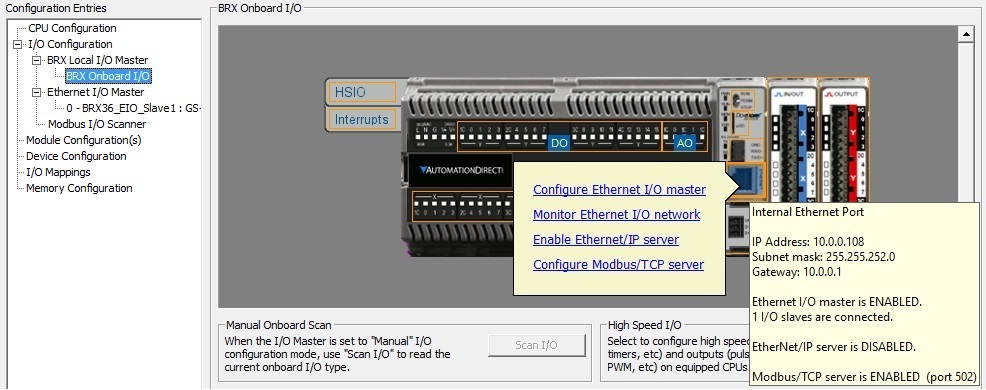
Expanding any of I/O Master entries and selecting one of the PLC system items will display a graphical view of the PLC system including the CPU, the on-board I/O (if present), any installed I/O modules, and if the Ethernet I/O Master is enabled, each expansion I/O Slave is shown with the I/O they have installed.
Hovering the mouse cursor over the graphic will cause an orange outline to appear over important areas of the CPU, the on-board I/O, and the I/O Modules. Hovering the mouse cursor over any of the highlighted areas will generate a pop-up tool tip that will display the current configuration of the highlighted object. Left-clicking on any of the highlighted objects will display a pop-up menu of selections for configuring the selected object.
While the cursor is hovering over an I/O Module the pop-up tool tip will display the module's part number, where it's currently mapped, and its power budget consumption.
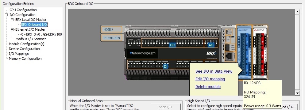
Right-clicking on the module will display a list of operations that can be performed on that module.
Depending on the PLC family that list will contain one or more of the following:
See I/O in Data View - open a new Data View that contains all of the I/O points on the selected I/O Module with Status enabled.
Edit I/O Mapping - open the I/O Mapping page of the System Configuration so you can change the module 's current map location.
Optional (DL205 Systems only) - marks the I/O module as optional, this is discussed in detail below.
Delete Module - remove this I/O module from the base (only applicable if the I/O Master's Configuration Mode is set to "manual").
Read Module Name - reads the part number of an I/O module based on the module ID read from that slot.
Configure Module - opens the appropriate configuration dialog (only enabled for I/O modules that must be configured prior to use).
View Manual - opens a submenu where the actual part number of the I/O module can be selected, this will then open the default web browser, which will then open a page on Automationdirect's web site that contains links to the User Manual. This requires a functioning connection to the Internet.
View Specs - opens a submenu where the actual part number of the I/O module can be selected, this will then open the default web browser, which will then open a PDF file on Automationdirect's web site that displays the specification pages from the catalog. The Spec pages contain hardware requirements and wiring diagrams. This requires a functioning connection to the Internet and a PDF viewer.
Manual I/O Configuration Options
If the I/O Master's Configuration Mode is set to Manual you can perform the following actions:
(DL205 Systems Only) Manually Scan for Base Contents
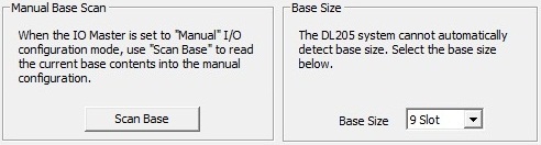
Click the Manual On-board Scan / Manual Base Scan button to scan the on-board I/O or I/O modules in the local base and store the current base contents in the manual I/O configuration.
Base Size is only used in DL205 systems which cannot automatically detect the size (number of slots) in a given base; this selection provides a way to change the graphical view so that it matches the actual size of the base. Select the 3 Slot, 4 Slot, 6 Slot, or 9 Slot option from the drop-down list. The initial list of optional base sizes will change based on the number of modules detected in the base.
How to Delete the Configuration for an Installed Module
If the I/O Master's Configuration Mode is set to "manual", right-clicking on the installed module's graphic and select Delete Module from the pop-up menu will remove the current I/O module definition from the I/O configuration.
(DL205 Systems Only) How to Mark a Module as Optional
If the I/O Master's Configuration Mode is set to "manual", right-clicking on the installed module's graphic and select Optional from the pop-up menu will mark this module as Optional meaning that it will not be considered when the manual I/O configuration is compared to the I/O configuration read from the system during a Program-mode to Run-mode transition. The I/O space consumed by a module configured as optional is retained so that the I/O mapping does not change.
Note: I/O modules that are configured to be optional will be marked with the word "* Optional *" in yellow on the graphical view.
Note: The instruction HWINFO - Get Hardware Information can be used to detect the presence of I/O modules marked as 'Optional' as a way to programmatically control optional execution schemes.
How to Manually Add a Module in a BRX System
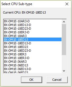
Because most of the BRX PLCs have some amount of on-board I/O, the exact model number of the PLC is required to present the correct amount and type of I/O in the system configuration. If you are online with the BRX PLC, the correct model number is select by Do-more Designer when the communication session was first initiated. But if you are offline, you must select the proper model number as part of the New Project definition. If for any reason you need to change the PLC type that was initially selected, you can right-click anywhere on the PLC graphic and the popup menu will contain an entry for Select CPU Subtype. Doing so will open the following dialog where you can select a different PLC model number:
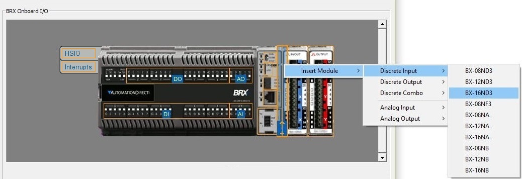
I/O modules are physically added to the BRX PLC by connecting them to the expansion I/O connector on the right side of the base in the desired order.
Do-more Designer allows I/O Modules to be manually added to the I/O configuration by inserting a new I/O module between existing I/O modules or by adding a new I/O module at the end. This is done by hovering the mouse cursor over the left or right edge of the I/O Module where the new module will be inserted. This action will draw a pale-blue rectangle with an orange outline. Right-clicking on that rectangle will display the Insert Module dialog; follow on to display a selection of I/O Module classes; follow on from there to display a list of the I/O modules in that class. Select the desired module part number in the resulting list and the selected I/O module will be inserted at that point.
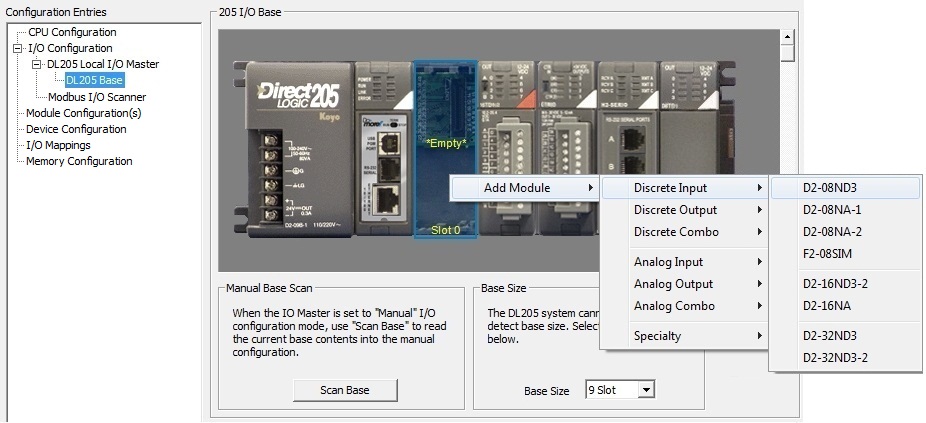
How to Manually Add a Module in a DL205 Base
The DL205 system uses bases that have a fixed number of I/O slots. Right-clicking on an Empty Slot will display the Add Module dialog, which will then display a selection of I/O Module classes. Select the appropriate class, and follow on to display a list of the I/O modules in that class. Select the desired module by part number in that list and that module will be added to the I/O Configuration.
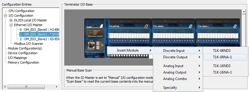
How to Manually Add a Module in a Terminator I/O System
Unlike the DL205 system, a Terminator I/O system (using either a T1H-DM1/E CPU or a T1H-EBC100 as an Ethernet I/O Slave) does not have a backplane with a fixed number of slots where I/O modules are inserted. I/O modules are physically added to the system by connecting their base pieces together in the desired order.
Do-more Designer allows I/O Modules to be manually added to the I/O configuration by inserting a new I/O module between existing I/O modules or by adding a new I/O module at the end. This is done by hovering the mouse cursor over the left or right edge of the I/O Module where the new module will be inserted. This action will draw an empty rectangle with a blue outline. Right-clicking on that rectangle will display the Insert Module dialog; follow on to display a selection of I/O Module classes; follow on from there to display a list of the I/O modules in that class. Select the desired module part number in the resulting list and that I/O module will be inserted at that point.
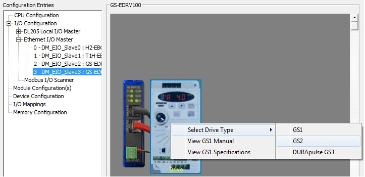
How to Manually Change the GS Drive Type
Right-clicking on the GS Drive picture will display the Select Drive Type dialog, follow on to display a list of the valid GS Drive types. Select the desired GS Drive type from the list and the drive picture will change to reflect the drive selected type.
Handling Runtime Errors from I/O Modules
Do-more Designer provides the I/O System View to monitor errors from I/O modules when it is connected to the Do-more CPU. This section details what the Do-more CPU provides to programmers that need to handle runtime reporting of errors from the I/O Masters, and the I/O modules that are under the control of any of the I/O Masters. There is a three tiered reporting scheme that reports I/O Master and I/O module errors at increasing levels of definition. This allows the programmer to handle these error condition at whatever level is deemed appropriate.
First Tier Reporting
The highest level of reporting is done through the System Bit $IOError (ST152), which is a single location that will be ON any time any of the I/O Masters in the system is reporting an error from one or more of its I/O Slaves or I/O modules. The Warning indicator will also be visible on the Status Bar, and the text "One or more IO masters are indicating a problem with a module - $IOError (ST152)" will be logged in the Warning Message section of the System Information dialog.
Second Tier Reporting
The middle tier of reporting is done through
the System structure $IOMasterErrors
(DST28), which is a DWord (32-bit) location that has one bit assigned
to each I/O Master in the system. The individual bit for an I/O Master
will be ON if any I/O module controlled by that I/O Master is reporting
an error.
Bit 0 is assigned to the Local I/O Master.
Bit 1 is assigned to the Ethernet I/O Master.
Additional Bits are assigned to additional I/O Masters in the order that they appear in the I/O Configuration list.
Third Tier Reporting
The third tier of error reporting is done through a System structure for each I/O Master.
The Local I/O Master can manage up to 128 slots of I/O modules; its structure has the following four DWord (32-bit) locations, with one bit assigned to each slot:
LocalIOMaster.Slot0_31 reports errors for slot 0 through slot 31
LocalIOMaster.Slot32_63 reports errors for slot 32 through slot 63
LocalIOMaster.Slot64_95 reports errors for slot 64 through slot 95
LocalIOMaster.Slot96_128 reports errors for slot 96 through slot 128
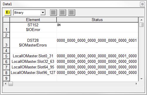
The following Data View shows these elements reporting the following error conditions:
There is an I/O Error ($IOError is ON).
The I/O Master that is reporting the error
is the Local I/O Master (bit 0 of $IOMasterErrors is ON).
The I/O Module that is reporting the error is in slot 5 (bit 5 of LocalIOMaster.Slot0_31 is ON).
Additional Error Reporting
The final error reporting is the error information from the I/O module itself. The amount of this data, the type of data, and how that data is presented to the Do-more CPU depends on the I/O subsystem the module is part of, and the individual I/O modules.
For modules that report error information through status bits and / or alarm bits (for example the analog input modules), those bits are automatically placed in the Discrete Input range (X) at the same time the values for the actual I/O channels are placed in their proper memory locations - refer to the chart for Analog I/O Module Mapping and Discrete I/O Module Mapping for details on the number of alarm and status bits that are allocated for a particular module.
Details on what each of those bits indicates is module-specific; that information must be referenced from the Analog and Discrete I/O Module chapters of the Do-more H2 Series PLC Hardware User Manual (Automationdirect.com Part #: H2-DM-M) or the Do-more Terminator Series PLC Hardware User Manual (Automationdirect.com Part #: T1H-DM-M).
For debugging purposes, the I/O System View provides detailed error and warning information from I/O modules in the local base and from Ethernet I/O Slave devices and their I/O Modules.
See Also:
EtherNet/IP Server / Adapter Configuration
I/O Configuration
Ethernet I/O Master Configuration
Modbus I/O Scanner Configuration