Topic: DMD0419

BRX On-board I/O
There are many different models of BRX PLCs, each with different amounts and types of on-board I/O. Because of the variety of I/O configurations, there may one or more of the types of the on-board I/O that needs to be configured before it can be used in the project.
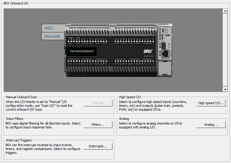
Input Filters
The on-board discrete inputs on all of the BRX hardware platforms can be configured to use input filtering. Filters like this are typically used on inputs that are operating in electrically noisy environments to remove both "false positives" and "false negatives". They do this by requiring that the input signal for a discrete input must remain above or below the input's hardware threshold level longer than the filter time before the CPU will see the state change. Once the state change is recognized, it must remain at the opposite level longer than the filter time before the CPU will see the opposite state.
Interrupt Triggers
A PLC normally reads its inputs at the top of the scan and writes its outputs at the bottom of the scan, the ladder logic is solved after the inputs are read and the outputs are written. Because the PLC can change the amount of work it does from scan to scan, the PLC's scan time will also change accordingly, which will directly affect the frequency that inputs can be read and outputs can be written. BRX PLCs use interrupts to do work that has to occur regardless of variations in the PLC scan time. Discrete Input Interrupts can be used to respond to transitions of discrete inputs that occur during a PLC scan. Value Match Interrupts can respond to specific values in specified registers. Timed Interrupts can be used to turn discrete outputs ON or OFF at specified regular intervals or at a specified delay time. When an interrupt occurs the BRX PLC will run a specified code block called an Interrupt Service Routine (ISR). BRX PLCs implement these interrupt events by creating an Interrupt Trigger that specifies the type of trigger, the required triggering conditions, and which Interrupt Service Routine to execute when that trigger is fired.
High-Speed I/O
On BRX PLCs with 24 VDC inputs, the first 10 of the on-board inputs (X0 - X9) - if it has that many are High-Speed inputs. These inputs are capable of working with 250 kHz inputs. These inputs are typically used for very fast input signals from external devices like encoders.
All BRX PLCs with 24 VDC outputs have High-Speed outputs. The first 1/2 of the on-board outputs (Y0 - Y1, Y0 - Y3, Y0 - Y7) are High-Speed. These outputs are capable of generating pulse trains in the range of 10 Hz to 250 kHz outputs @ 1m (100 kHz @10m or with a ZipLink .5m cable only). These very fast output signals are typically used for external devices like stepper motor drives.
Counter / Timer Functions - which can be configured as a high speed Counter that will count input pulses or as a high speed Timer that will measure the amount of time between successive input pulses up to a 250 kHz maximum pulse rate.
Axis / Pulse Outputs - which are typically used to drive stepper motors with a pulse frequency up to 250 kHz.
PWM (Pulse Width Modulated) Outputs - a High-Speed output can be used to generate a carrier frequency then vary the width of the pulses that are generated at that frequency.
Table Driven Outputs - use tables of preset values to turn the High-Speed outputs ON and OFF at various pulse count values of one of the High-Speed inputs.
Analog
Depending on which model of BRX CPU, there are 1 to 4 analog input channels located at WX0 through WX3. These channels can be configured to accommodate either Voltage or Current transducers. Each channel can optionally be scaled and the resulting floating point value placed in RX0 through RX3 respectively.
Depending on which model of BRX CPU, there are 1 or 2 analog output channels located at WY0 through WY1. These channels can be configured to drive either Voltage or Current transducers. Each channel can optionally be configured to receive a scaled floating point value from RY0 through RY1 respectively.
See Also:
BRX Pulse Width Modulated Outputs