Topic: DMD0303

STREAMIN - Stream in Data from Device
The Stream in Data from Device (STREAMIN) instruction is used to retrieve data from the internal buffer of a stream-capable input device (like a serial port or an Ethernet port), then store the data in either a String or a numeric data block. As its name implies, a stream-capable device is continually collecting input data from the port and storing it in an internal buffer. Each time this instruction is executed, up to 1024 bytes of data can be retrieved from that buffer, based on either a number of bytes, OR a set of termination delimiters, OR a timeout value.
Once retrieved from the internal buffer, the data is then stored in PLC memory. If the data destination is a String, up to 64 bytes can be placed into system-defined Short Strings (SS), or system-defined Long Strings (SL), and up to 1024 bytes can be placed in user-defined Strings. If the data destination is a Numeric Data Block (byte buffer), up to 1024 bytes can be placed in the data block (a new data block of Bytes can be created in the instruction editor).

Element References:
Note: Use the F9 key or click the 'three dot box' at the right edge of the parameter field to open the Default Element Selection Tool (the Element Picker or the Element Browser) or use the Down-Arrow key (Auto-Complete) on any parameter field to see a complete list of the memory locations that are valid for that parameter of the instruction.
Device specifies which stream device to read the input data from.
Serial Port Devices selects a device configured to use the on-board serial port, a serial port POM, or one of the serial ports on a SERIO module.
Ethernet Devices selects a device that is configured to use the on-board Ethernet port.
create device will open the New Device configuration page of the System Configuration dialog where a stream device can be created.
Complete When ... is a group of options that set conditions that will signal the completion of the STREAMIN instruction. Any combination of the following three options can be used to signal the completion of the instruction:
Length specifies the minimum number of characters that must be available in the stream device's input buffer to satisfy this condition. This can be a constant value from 1 to 1024, or a numeric location with a value in that range. This value specifies how many characters will be retrieved from the stream device's input buffer, so the Data Destination must be capable of storing that number of bytes. Up to 64 bytes be placed in a String Short (SS) data type, up to 256 bytes can be in a String Long (SL) data type, and up to 1024 bytes can be in a user-defined String (which was created in System Configuration -> Memory Configuration -> Add Memory Block.
If the Length condition is met, the data from the beginning of the stream device's input buffer to the specified number of bytes is moved from the stream device's input buffer to the Data Destination location. Any data that remains in the stream device's input buffer will be shifted to the beginning of that buffer.
Delimiters specifies from one to three characters that signal the completion of the instruction.
If the Delimiters condition is met, the data from the beginning of the stream device's input buffer to the specified character is moved from the stream device's input buffer to the Data Destination location. Any data that remains in the stream device's input buffer will be shifted to the beginning of that buffer.
select Exact Sequence if the specified characters must be receive in the order specified.
select Any One Delimiter if receipt of any of the specified characters will signal completion.
Trim Delimiter(s) from Output String specifies whether the delimiter character should be stored along with the input data, or removed from the input data before it's moved to the specified Output String.
Network Timeout is the maximum amount of time (in milliseconds) to allow the STREAMIN instruction to wait for the termination condition to be met. This value is a constant in the range of 1 to 65535.
If the Network Timeout condition is met, any data in the stream device's input buffer will remain in that buffer. In response to error conditions, or protocol initialization concerns, the Clear Device (DEVCLEAR) instruction can be used to clear all of the data from the stream device's input buffer.
Advanced: the Advanced Settings dialog contains some optional post-processing operations that this instruction can perform on the input data before the data is stored in the destination location.
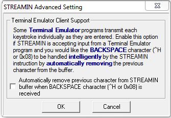
The Terminal Emulation Client Support allows this instruction to perform some extra processing of the input data if the source of that data is a terminal emulator program. Enabling this option will perform a 'backspace' operation if a CTRL-H (0x08) character is received by removing the previous character in the input data buffer before the data buffer is stored in the destination location. If this option left is disabled, no post-process any of the data will occur; both the previous character and the 'backspace' character (CTRL-H) will remain in the input data buffer and both characters will be stored in the Data Destination location.
Data Destination selects where to store the data that has been read from the stream device. The option chosen will depend on the type of data that is received from the Stream Device. If the data is ASCII text the appropriate choice is String Structure. If the data is binary, or simple bytes of data the appropriate choice is a numeric block of bytes.
- Select String Structure and specify a String
where the data read from the Stream Device will be stored. This can be any of the system-defined Short Strings (SS, up to 64 bytes), or system-defined Long Strings (SL, up to 256 bytes), or a user-defined String, which can be a maximum of 1,024 bytes.
-
Select Numeric Data Block and specify a memory block to store the data read from the Stream Device.
Many communication protocols are constructed using Bytes of data, but the Do-more CPU does NOT have a preconfigured block of Unsigned Bytes. If a Byte buffer is needed, clicking Create Byte Buffer will open the Create Unsigned Byte Buffer Block dialog where one can be created.
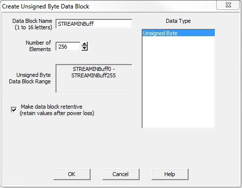
The Data Block Name (1 to 16 letters) must be unique, and consist of 1 to 16 characters (A-Z, a-z; no numbers, no spaces). The default name STREAMINBuff can be changed if desired.
Number of Elements specifies the size of the data block to create up to maximum of 1024 bytes. Data blocks must be created on a DWord (4-byte) boundary.
Unsigned Byte Data Block Range displays the first and last element of the block that will be created based on the current entries for Data Block Name and Number of Elements.
Data Type selects what type of data block will be created, the only selection is Unsigned Bytes.
Make data block retentive (retain values after power loss): a data block marked as retentive will hold its state through a power cycle or a Program-to-Run mode transition. The status of memory NOT marked as retentive will be cleared at power up and during a Program-to-Run mode transition.
Start Address is the offset into an existing numeric data block to begin storing the data read from the stream device.
Buffer Size in Bytes is the maximum number of Bytes of data that can be placed in the data block. This can be any numeric location or any constant value. This value is NUMBER OF BYTEs; for data block of Words there are 2 Bytes per element, for DWord data blocks there are 4 Bytes per element.
Number of Bytes to Read specifies a numeric memory location to store the number of bytes that were read from the stream device and stored in the designated location. This can be any writable numeric location.
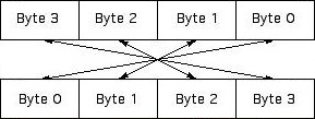
Endian Settings specify any optional processing to handle the Byte and Word ordering of the data, typically to handle big-endian / little-endian issues:
Enable Swap Byte to swap the Bytes in each Word of data.
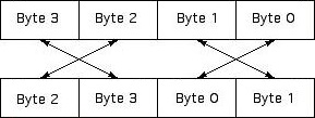
Enable Swap Word to swap the Words in each DWord of data.
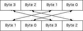
Enable both options to swap the Bytes in each of the Words AND swap the Words in each of the DWord elements, which reverse the Byte order in a DWord.
The On Success and On Error parameters specify what action to perform when this instruction completes. You do not have to use the same type of selection for both On Success and On Error.
If the Set Bit selection is used for either On Success or On Error, the specified BIT location will be SET OFF when the instruction is first enabled and will remain OFF until the instruction completes. Once complete, the appropriate Success or Error bit location ON. The specified Bit location is enabled with a SET (Latch) operation meaning that it will remain ON even if the input logic for the instruction goes OFF.
If the JMP to Stage selection is used for either On Success or On Error the target Stage must be in the same Program code-block as this instruction, you cannot specify a target Stage that exists in a different Program code-block. When the operation finishes, the target Stage will be enabled the same way as a standalone Jump to Stage (JMP) instruction would do it. The JMP to Stage option will only be available if this instruction is placed in a Program code-block.
On Success selects which of the following actions to perform if the operation is successful:
- Enable SET Bit then specify any writable bit location.
- Enable JMP to Stage then specify any
Stage number from S0 to S127 in the current Program code-block.
On Error selects which of
the following actions to perform if the operation is unsuccessful:
- Enable SET Bit then specify writable bit location.
- Enable JMP to Stage then specify any Stage number from S0 to S127 in the current Program code-block.
If either the On Success or On Error selections are set to JMP to Stage, Automatically create the SG box for any NEW stage number will be enabled which will automatically create any target stage that does not already exist.
- Below this rung will create the new target stage on a new rung following this instruction.
- At end of code-block will create the new target stage as the last rung of this Program.
Stream Device Structure Fields:
A STREAMIN instruction will reference a Stream Device![]() A pre-configured device that is capable of communicating via connection-oriented protocols like Modbus TCP/IP (over Ethernet) or Modbus/RTU (over serial). . Each Stream device has an associated structure which contains the following member fields:
A pre-configured device that is capable of communicating via connection-oriented protocols like Modbus TCP/IP (over Ethernet) or Modbus/RTU (over serial). . Each Stream device has an associated structure which contains the following member fields:
.InQueue (Read / write) is a 16-bit unsigned value that is the number of bytes of data in the Input Buffer.
.OutQueue (Read / write) is a 16-bit unsigned value that is the number of bytes of data are in the Output Buffer.
.Open (Read only) is a Bit location that will be ON if a call to a device opening instruction has been made (e.g. Open TCP Connection has been executed and a corresponding Close Device has NOT been executed).
.Connected (Read only) is a Bit location that will be ON if the TCP Port Number (TCP socket) is actively connected to its communication partner (only applicable for TCP Client devices).
.CTS (Read only) is a Bit location that will be ON if the CTS line of the serial port is high.
.RTS (Read / write) is a Bit location that is used to turn the RTS line of the serial port ON (high) or OFF (low).
Status Display:

The red triangle in the upper left corner of the status display indicates this is a Fully Asynchronous instruction.
The gray triangle at the right end of the input leg indicates the input is edge-triggered, meaning this instruction will execute each time the input logic transitions from OFF to ON.
The Status display for the String or Numeric Block will only display as many of the characters of the destination location as will fit within the borders of the instruction, typically this is about 50 characters.
See Also:
STREAMIN - Stream In Data from Device
STREAMOUT - Stream Out Data to Device
Related Topics:
PACKETIN - Input Data from Packet Device
PACKETOUT - Output Data to Packet Device
Example Using Stages:
If the PLC is a TCP ASCII Slave use (TCPLISTEN) Start Listening a TCP Port to open the port, and if that instruction completes successfully, use a STREAMIN to just receive data, or STREAMIN / STREAMOUT pair to receive, then respond.
If the PLC is a TCP ASCII Master use an OPENTCP Open TCP Connection to open the port, and if that instruction completes successfully, use a STREAMOUT to just send data, or STREAMOUT / STREAMIN pair to send then receive.
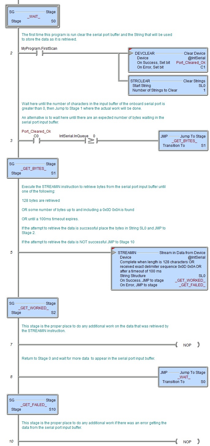
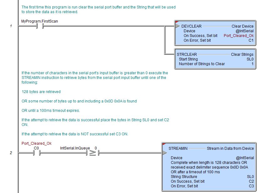
Rung Example: