Topic: DMD0182

SETUPSER - Setup Serial Port
The Setup Serial Port (SETUPSER) instruction is used to set the communication parameters of the on-board serial port of a Do-more CPU, any of the ports on a SERIO module, and the serial port POMs for a BRX PLC.
Parameters:
Note: Use the F9 key or click the 'three dot box' at the right edge of the parameter field to open the Default Element Selection Tool (the Element Picker or the Element Browser) or use the Down-Arrow key (Auto-Complete) on any parameter field to see a complete list of the memory locations that are valid for that parameter of the instruction.
Device - selects which Serial Port device to configure.
@IntSerial - the on-board serial port.
@POM - a serial POM for a BRX PLC.
create module - selecting this option will open the Module Configuration dialog in the System Configuration where a new serial module configuration can be created.
Baud Rate - selects 1200, 2400, 4800, 9600, 19200, 38400, 57600, 115200 as the baud rate.
Data Bits - selects either 7 or 8 data bits.
Stop Bits - selects either 1 or 2 stop bits.
Parity - selects either Odd, Even or None for the parity bit.
Transmit Control - selects when data that appears in the port's receive buffer will be sent.
-
Unconditional - data will be sent as soon as it appears in the port's send buffer.
-
Wait for CTS - data will not be sent until the CTS line is asserted.
-
Delayed 5ms - data will not be sent until 5 ms after the RTS line is asserted.
-
Delayed 50ms - data will not be sent until 50 ms after the RTS line is asserted.
-
Delayed 250ms - data will not be sent until 250 ms after the RTS line is asserted.
-
Delayed 500ms - data will not be sent until 500 ms after the RTS line is asserted.
Note: selecting any of the Delay options will force the RTS Control selection to Follow Transmitter because the port needs to have complete control of the RTS line.
RTS Control - selects how the RTS line behaves
-
Follows Transmitter - the RTS line is asserted whenever there is data to be sent. Selecting Wait for CTS and Follows Transmitter for RTS Control effectively sets up the serial port for 'hardware flow control'.
-
Manual - puts the RTS line under control of the ladder logic program (use the DEVREAD - Read Device Register and DEVWRITE - Write Device Register instructions to manually control the RTS line)
-
On - unconditionally sets the RTS line ON.
-
Off - unconditionally sets the RTS line OFF.
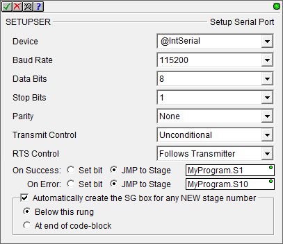
The On Success and On Error parameters specify what action to perform when this instruction completes. You do not have to use the same type of selection for both On Success and On Error.
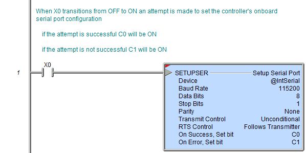
If the Set Bit selection is used for either On Success or On Error, the specified BIT location will be SET OFF when the instruction is first enabled and will remain OFF until the instruction completes. Once complete, the appropriate Success or Error bit location will be set ON. The specified Bit location is enabled with a SET (Latch) operation (not an OUT operation) meaning that it will remain ON even if this instruction's input logic goes OFF.
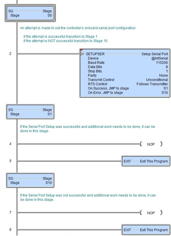
If the JMP to Stage selection is used for either On Success or On Error the target Stage must be in the same Program code-block as this instruction, you cannot specify a target Stage that exists in a different Program code-block. When the operation finishes, the target Stage will be enabled the same way as a standalone Jump to Stage (JMP) instruction would do it. The JMP to Stage option will only be selectable if this instruction is placed in a Program code-block.
On Success selects which of the following actions to perform if the operation is successful:
- Enable Set Bit then specify any writable bit location.
- Enable JMP to Stage then specify
any Stage number from S0 to S127 in the current Program code-block.
On Error selects which of
the following actions to perform if the operation is unsuccessful:
- Enable SET Bit then specify writable bit location.
- Enable JMP
to Stage then specify any Stage number
from S0 to S127 in the current Program code-block.
If either the On Success or On Error selections are set to JMP to Stage, Automatically create the SG box for any NEW stage number will be enabled which will automatically create any target stage that does not already exist.
- Below this rung will create the new target stage on a new rung following this instruction.
- At end of code-block will create the new target stage on the last rung of this Program.
Status Display:
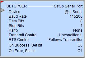
The red triangle in the upper left corner of the status display indicates this is a Fully Asynchronous instruction.
The gray triangle at the right end of the input leg indicates the input is edge-triggered, meaning this instruction will execute each time the input logic transitions from OFF to ON.
See Also:
Setup Serial Ports in the System Configuration
Setup Serial Ports POMs in the System Configuration
Related Topics:
SETUPIP - Setup TCP/IP Parameters
SETUPNOD - Setup Ethernet Node Parameters
Example Using Stages:
Rung Example: