Topic: DMD0493

Modbus I/O Scanner Configuration
BRX CPUs can use a Modbus I/O Scanner to process Modbus Read and Modbus Write requests similarly to the way it handles local I/O and Ethernet Remote I/O. It does this by creating a Scanner Device for any combination of up to 32 Modbus/TCP or Modbus/RTU servers. The Scanner Device can additionally perform any required format conversion on the data, removing the need to add ladder logic to process the data before it is sent or after it is received.
In PROGRAM mode, the Modbus I/O Scanner will process all of the Modbus Reads for all of the configured Scanner Devices, but the Modbus Writes will NOT be processed. When the CPU transitions to RUN mode, the Modbus I/O Scanner will begin processing the Modbus Writes in addition to the Modbus Reads.
The Modbus I/O Scanner continuously processes the Reads and Writes for the Scanner Devices. But in many applications, there will be some Modbus Reads and Writes of the Modbus server that only need to occur when an event happens. The MSREGRD - Modbus I/O Scanner Register Read and MSREGWR - Modbus I/O Scanner Register Write instructions are used to interleave event-based Reads and Writes with the Modbus I/O Scanner's regular communication work.
Creating Scanner Devices
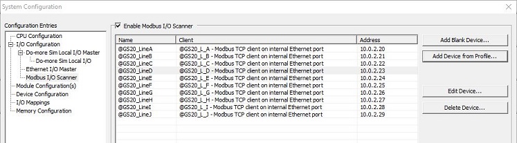
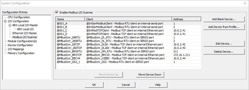
The Modbus I/O Scanner processes communication requests for up to 32 Scanner Devices, each of which uses a Modbus/RTU or Modbus/TCP Client device to communicate with a target Modbus Server. Scanner Devices can be created using the following two methods:
Using a profile that was created for a specific Modbus Server. A profile defines the Modbus Reads and Writes that will be processed, where the data for these Reads and Write are sourced from or stored to as appropriate, and any byte-swapping / word-swapping or scaling that may be needed as part of the Read or Write operation. A profile can be built so that it uses either a user-defined data structure or built-in memory blocks for storing the Scanner Device's data.
There are system profiles (*.mdp) that are provided with the Do-more Designer software for many of the Modbus Server devices that are sold by Automationdirect.com. Scanner Devices built with a system profile will have a fixed configuration that cannot be altered to include additional comm requests, or delete existing comm requests, or change the PLC memory storage configuration.
There are also user profiles (*.mup) that are built by the Scanner Device configuration utility from the Modbus Read, Modbus Write, and mapping information supplied by the user when the Scanner Device is created.
Note: a system profile can be used as a template for a user profile (*.mup) by using Generate Profile from Config after the system profile has been loaded.
Starting with a blank device which has no predefined communication requests, and manually adding the required Modbus Read requests, Modbus Write requests, and the associated mapping for PLC data storage locations for the Modbus Server. Once a blank Scanner Device has been created, the configuration of that device can be used to build a user profile (*.mup), which can the be used to create additional Scanner Devices that target Modbus Servers of the same type.
Monitoring the Scanner's Communications
After the Modbus Scanner is configured and running, the Modbus I/O Scanner Monitor can be used to display the "health" of the currently configured network of Scanner Devices, and to provide some manual control of the Scanner Devices at runtime. This utility is opened by selecting the Debug -> Modbus Scanner Monitor menu selection.
Adding a Scanner Device with a Profile
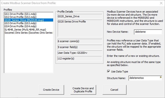
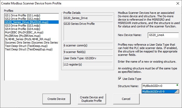
Selecting Add Device from Profile... will open a dialog where a new scanner device can be created using a system-provided profile (*.mdp) or a user-created profile (*.mup). Profiles contain the Modbus read and Write requests and their related mapping to the PLC's memory (either a structure or memory blocks). System profiles are read-only.
The Profiles section lists the profiles found in the <public documents>\Do-more\Profiles folder. The particulars of the highlighted profile will be shown in the Profile Details section that contains predefined Modbus Read and Write requests and their related mapping to the PLC's memory (either a data structure or memory blocks).
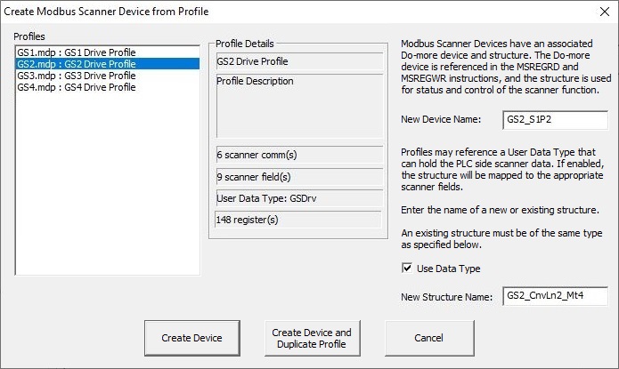
After selecting a profile to use, enter a unique name for the new scanner device in the New Device Name field. Scanner Device names must be unique and must follow Nickname rules![]() Nicknames can be 1 to 16 characters in length and consist of any combination of alphanumeric characters and underscores ('_', 'a-z', 'A-Z', 0-9), no spaces or punctuation marks are allowed, and must begin with a letter or an underscore. because the Scanner Device will have an associated structure by the same name whose fields are used for status and runtime control of the Scanner Device.
Nicknames can be 1 to 16 characters in length and consist of any combination of alphanumeric characters and underscores ('_', 'a-z', 'A-Z', 0-9), no spaces or punctuation marks are allowed, and must begin with a letter or an underscore. because the Scanner Device will have an associated structure by the same name whose fields are used for status and runtime control of the Scanner Device.
If the profile was built using a user-defined structure, the Use Data Type option will be enabled, and you will need to enter a New Structure Name, which will be the new data structure this Scanner Device will create and use for its data storage. An existing data structure can be used IF that structure is of the same type used in the profile. If the profile was built using memory blocks (C, D, N, R, etc.), the Use Data Type selection will be disabled.
Click Create Device to create the new Modbus I/O Scanner Device using the Comms and Fields defined in the profile. This is the typical workflow for using a System Profile (*.mdp) to create one or more Scanner Devices.
Click Create Device and Duplicate Profile to create the new Scanner Device using the Comms and Fields in a System Profile (*.mdp) or a User Profile (*.mup) as a template for a new profile. This is the typical workflow when you intend to use an existing profile as a template, then change the duplicated profile by adding additional Comms / Fields, changing any of the existing Comms / Fields, or removing some of the existing Comms / Fields. You will be prompted to name the new profile before continuing.
Note: if you will be creating multiple Scanner Devices of the same type, and you will need to iterate through the multiple devices, you might consider creating a new memory block of the scanner devices which will make iterating them much easier. Refer to the App Note at the end of this topic for the steps needed to do this.
Click Cancel to abort without creating the Scanner Device or the new data structure.
Scanner Device Configuration
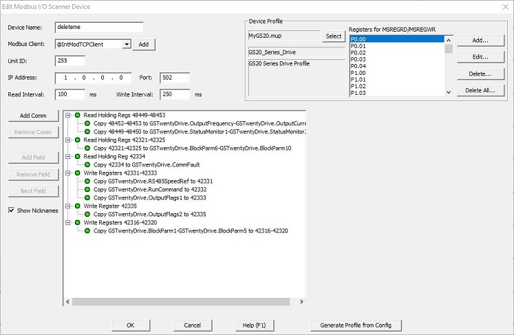
Both Create Device and Create Device and Duplicate Profile will open the following dialog to enter the remaining data needed to build the new Scanner Device with its associated data structure.
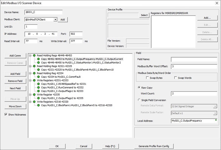
The Device Name is the name entered on the previous dialog for this device.
Select the Modbus Client this scanner device will use to communicate to the Modbus Server. Click the Add button to the right of the list to open the Create New Device dialog where a new Modbus Client can be created if needed.
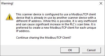
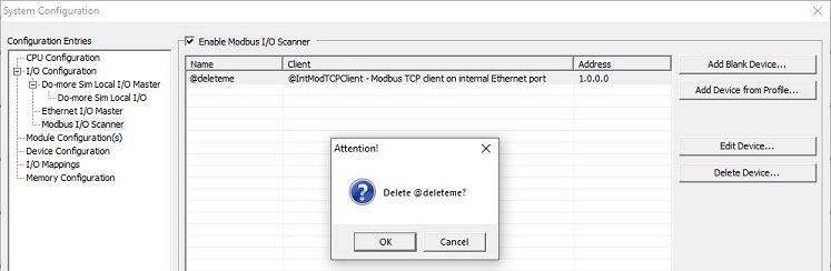
Note: if the selected Modbus Client is configured to use Modbus/TCP protocol, having multiple Modbus I/O Scanner Devices use the same Modbus/TCP Client Device will work, but the overhead of managing the TCP connection each time the Modbus Client is accessed by a different Modbus Scanner significantly increases the PLC scan time. Therefore it is highly recommended that a unique Modbus/TCP Client be created for each Modbus/TCP Server. Any attempt to create a new Modbus I/O Scanner Device that is configured to use a Modbus/TCP Client Device that is already in use will prompt the user with the following confirmation dialog:
If the Modbus Client uses Modbus/RTU protocol (over a serial connection), enter the Unit ID that uniquely identifies the Modbus/RTU server on the serial network.
If this Modbus Client uses Modbus/TCP protocol (over an Ethernet connection), the IP Address and the Port number of the Modbus Server identify the Modbus/TCP server or Modbus Gateway.
Note: if the Modbus Client is working through a Modbus Gateway, you will need to enter both the IP Address and the Port number of the Gateway, and the Unit ID that uniquely identifies the Modbus/RTU server on the serial side of the Gateway.
The Read Interval specifies how often the Modbus I/O Scanner will process the Comm requests in this scanner device that read from the configured Modbus server.
The Write Interval specifies how often the Modbus I/O Scanner will process the Comm requests in this scanner device that write to the configured Modbus server.
Because this Scanner Device is built with a system profile, no other configuration is required - or allowed (because it is read-only) - to complete the setup.
The Device Profilesection of the dialog is not used to create a Scanner device; it can only be used to explore the contents of the System Profile in use. The Comm and Field sections are also disabled because no changes can be made to the Scanner Device configuration. Click Ok to create the Scanner Device, or Cancel to abort.
Adding a Scanner Device without using a Profile
Selecting Add Blank Device... will open a dialog where a new Scanner Device can be created that has no predefined communication requests.
Note: if you will be creating multiple Scanner Devices of the same type, and you will need to iterate through the multiple devices, you might consider creating a new memory block of the scanner devices which will make iterating them much easier. Refer to the App Note at the end of this topic for the steps needed to do this:
![]()
The Device Name shows the name that was created for this device.
Select the Modbus Client this scanner device will use to communicate to the Modbus Server.
Click the Add button to the right of the list to open the Create New Device dialog where a new Modbus Client can be created if needed.
Note: if the selected Modbus Client is configured to use Modbus/TCP protocol, having multiple Modbus I/O Scanner Devices use the same Modbus/TCP Client Device will work, but the overhead of managing the TCP connection each time the Modbus Client is accessed by a different Modbus Scanner significantly increases the PLC scan time. Therefore it is highly recommended that a unique Modbus/TCP Client be created for each Modbus/TCP Server. Any attempt to create a new Modbus I/O Scanner Device that is configured to use a Modbus/TCP Client Device that is already in use will prompt the user with the following confirmation dialog:
If the Modbus Client uses Modbus/RTU protocol (over a serial connection), enter the Unit ID that uniquely identifies the Modbus/RTU server on the serial network.
If the Modbus Client uses Modbus/TCP protocol (over an Ethernet network), enter the IP Address and the Port number that uniquely identifies the Modbus/TCP server on the Ethernet network.
Note: if the Modbus Client is working through a Modbus Gateway, you will need to enter both the IP Address and the Port number of the Gateway, and the Unit ID that uniquely identifies the Modbus/RTU server on the serial side of the Gateway.
The Read Interval specifies how often the Modbus I/O Scanner will process the Comm requests in this scanner device that read from the configured Modbus server.
The Write Interval specifies how often the Modbus I/O Scanner will process the Comm requests in this scanner device that write to the configured Modbus server.
The Comm and Field sections are used to configure the Scanner Device. The Device Profilesection of the dialog is not used to create a Scanner Device. Refer to the Adding Comm Requests and Associated Field Mapping section below for details on adding new Comm and Field entries. When the configuration is complete, click Ok to create the Scanner Device, or Cancel to abort.
Adding Comm Requests and Associated Field Mapping
Click Add Comm to create a new Modbus Read or Modbus Write request for this Scanner Device.
Function Code: selects which of the Modbus Function codes this Comm operation will use. There are four supported Modbus Read Function Codes: 1 - Read Coils, 2 - Read Discrete Inputs, 3 - Read Holding Registers, and 4 - Read Input Registers, and four supported Modbus Write Function Codes: 5 - Write Single Coil, 6 - Write Single Register, 15 - Write Multiple Coils, and 16 - Write Multiple Registers.
Offset Address: is the offset to the first data value in the Modbus server for this Comm request.
Count: specifies the number of contiguous values, beginning at the Offset Address, for this Comm request.
The Modbus Address field will display the range of the Comm request as defined by the current Function Code + Offset + Count values entered.
Click Remove Comm to delete the highlighted Modbus Read or Write request. Note: any Field mappings that are associated with the Comm request will also be deleted.
Highlight one of the Comm operations then click Add Field to create a mapping from the Comm request to memory locations in the PLC for the data in the highlighted Comm request.
The Field Name is a user-assigned name for this Field in this Comm request. Data entered in this field will be stored in a profile.
The Modbus Buffer Word Offset is the offset in the Comm Request buffer to the data for this field.
The Modbus Data Byte / Word Order selections allow the Bytes and / or Words of the Register value to be reordered because of a difference in the Endianness of the Modbus server.
Enable only Byte Swap to swap the Bytes in each Word of the Comm request.
For example: ABCD EFGH --> CDAB GHEF
Enable only Word Swap to swap the successive Words in the Comm request.
For example: ABCD EFGH --> (swap words) --> EFGH ABCD
Enable both selections to swap the bytes in each Word and swap successive Words in the comm request, (this reverses the byte order of DWord value).
For example: ABCD EFGH --> (swap words) --> EFGH ABCD --> (swap bytes) --> GHEF CDAB
If needed, the next selection is used to convert from the data format used in the Modbus server to the data format of selected Local Address.
Selecting Raw Copy will use each element of the Comm request in the specified Local Address locations with no data conversion needed. The Range field will display the range of PLC address that will be used to stored the data based on the Word Count.
Selecting Single Field Conversion will perform the selected format conversion on the data before it is stored (if the Comm is a Modbus Read) or sourced from (if the Comm is a Modbus Write).
Remote Data Format specifies the format of the data in the Modbus server: 16-Bit Signed, 16-Bit Unsigned, 16-Bit BCD or 32-Bit Signed, 32-Bit BCD, 32-Bit Float (real).
If the Remote Data Format is an integer with implied decimal points and that value will be placed in Real memory (R), the Remote Scale Factor: is the number of implied decimal points in the value on the Modbus server: Default x1 (no implied decimal points), Implied by x 10 (one implied decimal point), Implied by x 100 (two implied decimal points), Implied by x 1000 (three implied decimal points).
Local Address: is the memory location in the PLC where the data for this field is stored (if the Comm is a Modbus Read) or sourced from (if the Comm is a Modbus Write). The proper PLC memory location depends on the Remote Data Format. The Local Address can be either memory blocks (C, D, R, N, etc. ) or structure fields of the appropriate type. Note: to use a structure for the local storage location, that structure must have already been created in the Memory Configuration of the System Configuration before it can be used by this Scanner Device.
Click Remove Field to delete the highlighted Field.
Clicking Next Field will move the highlight to the next Field; it will move to the next Comm request if the highlight is currently on the last Field in a Comm request.
When a Comm is selected, Move Up & Move Down will move the highlighted Comm entry (and all of its fields) within the Comm sub-tree.
When a Field is selected, Move Up & Move Down will move the highlighted Field within the Comm that contains the Field.
If Show Nicknames is enabled, the Nickname for any element that has one will be displayed instead of the element name.
Generate Profile from Config
Data entered in the Field Name for any field will be stored in a profile. If the profile does not exist, or if the profile exists and the text for a field name is changed, or when clicking Generate Profile button, the following dialog will be shown:
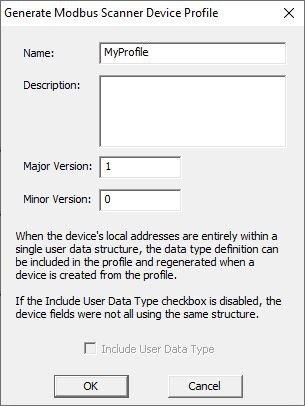
Name: is the file name for the profile. Profiles are stored in the <Public Documents>\Do-more\Profiles folder.
Description: describes the contents of the profile.
Major Version: / Minor Version: allow the user to assign a version to this set of contents of the profile.
Include User Data Type: will be enabled if all of the device's fields are using the same User Data Type; if this option is disabled, more that one User Data Type is being used by the profile. Checking this box will store a copy of the User Data Type in the profile.
Documenting Registers in a User Profile
The Device Profile section is used to manage the Registers that will be accessible when the profile is referenced while editing Modbus I/O Scanner Register Read (MSREGRD) and Modbus I/OScanner Register Write (MSREGWR) instructions.
Begin by clicking the Select button which will open a list of the profiles in Do-more Designer's Profile folder. Selecting one of the user profiles (*.mup), will enable Add..., Edit..., Delete..., and Delete All... buttons. Selecting a system profile (*.mdp) will disable these buttons because system profiles are read-only; you will only be able to see the registers listed in that profile.
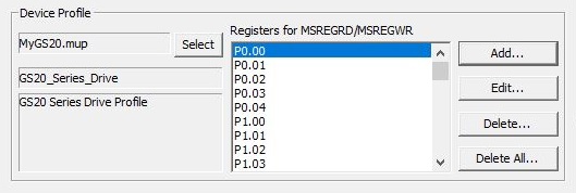
Highlight the profile that will contain the Register definitions then click the Select Profile button to open that profile and display the header information for that profile.
Clicking the Add... button will open the following dialog where a new Register, its documentation, and its remote data configuration can be added to the profile. Scrolling through the list of registers that clicking the Edit... button will open a similar dialog where that Register's documentation and remote data configuration can be changed.
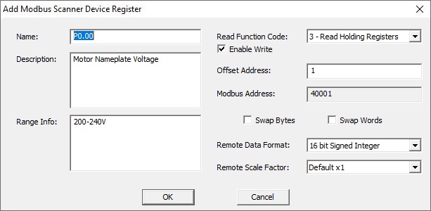
The Name, Description, and Range Info are user-assigned text fields for this Register definition.
Function Code: selects which of the Modbus Function codes will access this field. There are four supported Modbus Read Function Codes: 1 - Read Coils, 2 - Read Discrete Inputs, 3 - Read Holding Registers, and 4 - Read Input Registers.
The Enable Write option specifies whether the Register is Read-Write instead of Read-only.
The Modbus Address field will display the address that will be accessed as defined by the current Function Code + Offset Address values entered.
The Modbus Data Byte / Word Order selections allow the Bytes and / or Words of the Register value to be reordered because of a difference in the Endianness of the Modbus server.
Remote Data Format specifies the format of the data in the Modbus server: 16-Bit Signed, 16-Bit Unsigned, 16-Bit BCD or 32-Bit Signed, 32-Bit BCD, 32-Bit Float (real).
If the Remote Data Format is an integer with implied decimal points and that value will be placed in Real memory (R), the Remote Scale Factor: is the number of implied decimal points in the value on the Modbus server: Default x1 (no implied decimal points), Implied by x 10 (one implied decimal point), Implied by x 100 (two implied decimal points), Implied by x 1000 (three implied decimal points).
Clicking the Delete... button will remove the currently selected Register from the profile; you will be prompted to confirm.
Clicking the Delete All ... button will remove all of the Registers from the profile; you will be prompted to confirm.
Scanner Device Structure
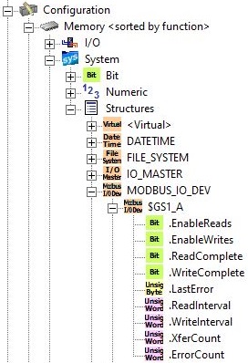
Each Scanner Device structure contains the following fields:
.EnableReads (read / write) will automatically be set ON when the PLC mode changes from PROGRAM to RUN, or from RUN to PROGRAM. When this bit is ON the Modbus I/O Scanner will process the Modbus Read requests for this Scanner Device. This bit can be manually turned OFF at runtime to stop processing the Read requests.
.EnableWrites (read / write) will automatically be set ON when the PLC mode changes from PROGRAM to RUN, and will automatically be set OFF the PLC mode changes from RUN to PROGRAM. When this bit is ON the Modbus I/O Scanner will process the Modbus Write requests for this Scanner Device. This bit can be manually turned OFF at runtime to stop processing the Write requests.
.ReadComplete (read / write) will be ON after one attempt of each Modbus Read request for the Device has completed; the bit will be ON whether the read requests completed successfully or not.
.WriteComplete (read / write) will be ON after one attempt of each Modbus Write request for the Device has completed; the bit will be ON whether the write requests completed successfully or not.
.LastError (read / write) contains the error code for the last Modbus Read or Write request that failed.
.ReadInterval (read / write) contains the number of milliseconds of time to delay between the Device's Modbus Read requests. Allowed range is 0 (no delay) to 65535 ms.
.WriteInterval (read / write) contains the number of milliseconds of time to delay between the Device's Modbus Write requests. Allowed range is 0 (no delay) to 65535 ms.
.XferCount (read / write) contains the number of completed Modbus Read and Write requests. This value rolls over after 65535.
.ErrorCount (read / write) contains the number of Modbus read and write requests that have failed. This value rolls over after 65535.
Error Codes for .LastError
The possible values for .LastError can be communication errors as reported in ERR System Error value (TIMEOUT, Invalid CRC, or Invalid Data). These values will be in the form of 80xx (Hex). A list of the possible communication errors can be found in the System Nicknames help topic (DMD0283) in the DST37 ($LastError) section.
If the .LastError value is not a communication error code, then it is a Modbus Exception code. Refer to the following table of Exception Response Codes:
See Also:
MSREGRD - Modbus I/O Scanner Register Read
MSREGWR - Modbus I/O Scanner Register Write
Related Topics:
EtherNet/IP Server / Adapter Configuration
Ethernet I/O Master Configuration
Modbus I/O Scanner Configuration
App Note: Creating a Block of Scanner Devices.
The Modbus I/O Scanner makes it very easy to consolidate communication to an array of Modbus servers, but many industrial networks will have multiple servers of the same type. This means multiple Modbus I/O Scanner devices will be using the profile to configure them. In these situations, using a memory block of data structures to store the scanner device's data can be a good option. Using a memory block has the added advantage of making it easy to iterate through the block of scanner device's data , for example: using a For / Next loop's Index to iterate through MyMemBlk[Index].Speed, MyMemBlk[Index +1].Speed, MyMemBlk[Index +2].Speed, etc..
What follows is a series of steps that will use the Scanner Device editor and a profile to create the User Data Type required for the scanner devices, create a memory block of those User Data Types, then create the scanner devices using offsets into that memory block.
-
Open the System Configuration, expand the I/O Configuration (if closed) then select Modbus I/O Scanner. Click the Enable Modbus I/O Scanner option, then choose Add Device from Profile. This will open the Create Scanner Device.
-
Select the profile that has the required Comms and Fields for the Modbus servers you will be controlling. Enter a temporary name in the New Device Name field, select Use Data Type ( if it is unselected), then enter a temporary for the Structure Name field; names you enter are unimportant as this device will deleted later. Click Create Device to continue.
-
On the scanner device editor, you will need to enter a temporary IP address because default Modbus Client is a Modbus TCP Client, simply change one number. Again, the IP address is unimportant as this device will deleted later.
-
Clicking OK will create this scanner device, but more importantly for our purposes, a User Data Type with the proper layout needed to store the data for this profile has been created.
-
-
Open the Memory Configuration editor and select the Memory Block tab.
-
Click the Add Memory Block button to open the dialog where the memory block of structures can be created.
-
Give the new memory block a name, then click the down arrow at the right end of the Data Type field to select the User Data Type that was created by the scanner device editor (the UDT will get its name from the profile that was selected). Choose the block size based on how many of the same type of scanner devices you will need; choose the Retentive Range setting that fits your needs, then click OK to create the new memory block.
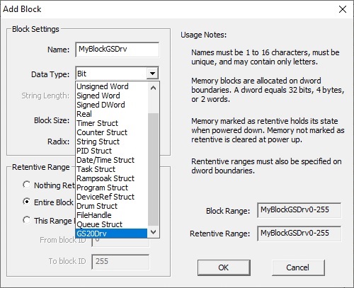
At this point we have a memory block of structures that match the layout of the Comms and Fields of the selected profile.
-
-
Return to the Modbus I/O Scanner section.
-
Now you can delete the temporary scanner device that was created earlier.
-
Now repeat the process used earlier to created a new scanner device. Starting with Add Device from Profile, then select the profile that was used before. This time though, enter the real name for the scanner device, select Use Data Type ( if it is unselected), then enter the name of the memory block that was just created, and the offset into that block for this particular scanner device (MyBlockGSDrv0, MyBlockGSDrv1, etc). Click Create Device to continue.
-
On the editor page, select the real Modbus Client and enter the required addressing information for the Modbus server this scanner device will be communicating with, then click OK to save this configuration.

-
You can now create the remaining scanner devices using the remaining memory block offsets.