Topic: DMD0304

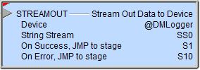
STREAMOUT - Stream Out Data to Device
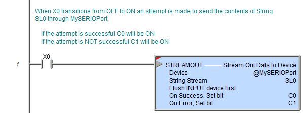
The Stream Out Data to Device (STREAMOUT) instruction is used to send data through to the specified, stream-capable device (like a serial port or an Ethernet port) from a String (if the data is ASCII text; maximum of 1024 bytes) or a numeric data block (if the data is binary; max of 1024 bytes). Up to 64 bytes can be sent from a String Short (SS) data type, up to 256 bytes can be sent from a String Long (SL) data type, and up to 1024 bytes can be sent from a user-defined String (which are created in System Configuration -> Memory Configuration -> Add Memory Block.
If the Data Source is a String you can use the Print to String (STRPRINT) instruction to build up the contents of the String. If the Data Source is a numeric data block containing binary data you can use the Put Bytes into a String (STRPUTB) instruction to store the bytes of data in the data block first.
Element References:
Note: Use the F9 key or click the 'three dot box' at the right edge of the parameter field to open the Default Element Selection Tool (the Element Picker or the Element Browser) or use the Down-Arrow key (Auto-Complete) on any parameter field to see a complete list of the memory locations that are valid for that parameter of the instruction.
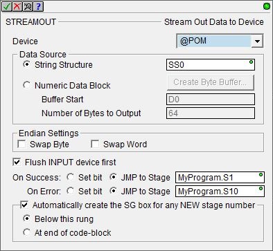
Device specifies which stream device will send the output data.
Serial Port Devices selects a device configured to use the on-board serial port, a serial port POM, or one of the serial ports on a SERIO module.
Ethernet Devices selects a device that is configured to use the on-board Ethernet port.
@DMLogger : Ethernet-equipped CPUs (DM1E) can send the output data to the Do-more Logger where it will be displayed. Displaying these runtime status or debug messages (also known as 'printf debugging') can be used for any number of reasons, including, tracing the execution path through a project, verifying intra-scan values of memory locations, etc. Follow this link for more information on using the DMLogger (Network Message Viewer).
@UserLog is similar in function to the DMLogger in that the output data can be sent to the User Log in the Do-more CPU. Theses messages can be viewed on the Event Logs tab of the System information utility. Follow this link for information on viewing the contents of the Event Logs with the System Information utility.
create device will open the New Device configuration page of the System Configuration dialog where a stream device can be created.
Data Source selects where the data to send to the stream device is currently stored. The option chosen will depend on the type of data that is to be sent by the stream device. If the data is ASCII text the appropriate location is a String Structure. If the data is binary or simple bytes of data the appropriate choice is a numeric block of bytes.
- Select String Structure and specify a String
where the data to send to the streaming device is stored. This can be any of the
system-defined Short Strings, or system-defined Long Strings, or any of
the user-defined Strings.
-
Select Numeric Data Block and specify the memory block where the data to send to the streaming device is stored.
Many communication protocols are constructed using Bytes of data, but the Do-more CPU does NOT have a preconfigured block of Unsigned Bytes. If a Byte buffer is needed, clicking Create Byte Buffer will open the Create Unsigned Byte Buffer Block dialog .where one can be created.
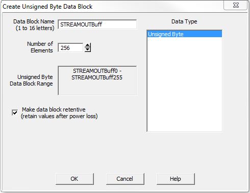
The Data Block Name (1 to 16 letters) must be unique, and consist of 1 to 16 characters (A-Z, a-z; no numbers, no spaces). The default name STREAMOUTBuff can be changed if desired.
Number of Elements) is the size of the data block to create. Data blocks must be created on a DWord (4-byte) boundary.
Unsigned Byte Data Block Range displays the first and last element of the block that will be created based on the current entries for Data Block Name and Number of Elements.
Data Type selects what type of data block will be created, the only selection is Unsigned Bytes.
Make data block retentive (retain values after power loss) means that a data block marked as retentive will hold its state through a power cycle or a Program-to-Run mode transition. The status of memory NOT marked as retentive will be cleared at power up and during a Program-to-Run mode transition.
Buffer Start is the offset in an existing numeric data block where the data to send to the stream device begins. This can be any numeric location or any constant value.
Number of Bytes to Output specifies the number of bytes to send to the stream device. This can be any numeric location or any constant value.
Endian Settings specifies
optional processing to handle the Byte and Word ordering of the data. Select both options to swap the Bytes in each of the Words and swap the
Words in each of the DWord elements.
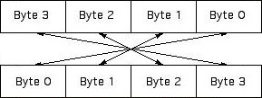
Enable Swap Byte to swap the Bytes in each Word of data.
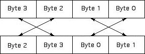
Enable Swap Word to swap the Words in each DWord of data.
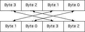
Enable both options to swap the Bytes in each of the Words AND swap the Words in each of the DWord elements, which reverse the Byte order in a DWord.
Flush INPUT device first: for Devices that have an input buffer (for example a serial port Device), optionally clear the Device's input buffer before sending the output data through that device.
The On Success and On Error parameters specify what action to perform when this instruction completes. You do not have to use the same type of selection for both On Success and On Error.
If the Set Bit selection is used for either On Success or On Error, the specified BIT location will be SET OFF when the instruction is first enabled and will remain OFF until the instruction completes. Once complete, the appropriate Success or Error bit location ON. The specified Bit location is enabled with a SET (Latch) operation meaning that it will remain ON even if the input logic for the instruction goes OFF.
If the JMP to Stage selection is used for either On Success or On Error the target Stage must be in the same Program code-block as this instruction, you cannot specify a target Stage that exists in a different Program code-block. When the operation finishes, the target Stage will be enabled the same way as a standalone Jump to Stage (JMP) instruction would do it. The JMP to Stage option will only be available if this instruction is placed in a Program code-block.
On Success selects which of the following actions to perform if the operation is successful:
- Enable SET Bit then specify any writable bit location.
- Enable JMP to Stage then specify any
Stage number from S0 to S127 in the current Program code-block.
On Error selects which of
the following actions to perform if the operation is unsuccessful:
- Enable SET Bit then specify writable bit location.
- Enable JMP to Stage then specify any Stage number from S0 to S127 in the current Program code-block.
If either the On Success or On Error selections are set to JMP to Stage, Automatically create the SG box for any NEW stage number will be enabled which will automatically create any target stage that does not already exist.
- Below this rung will create the new target stage on a new rung following this instruction.
- At end of code-block will create the new target stage as the last rung of this Program.
Stream Device Structure Fields:
A STREAMOUT instruction will reference a Stream Device![]() A pre-configured device that is capable of communicating via connection-oriented protocols like Modbus TCP/IP (over Ethernet) or Modbus/RTU (over serial)..
Each Stream device has an associated structure which contains the following member fields:
A pre-configured device that is capable of communicating via connection-oriented protocols like Modbus TCP/IP (over Ethernet) or Modbus/RTU (over serial)..
Each Stream device has an associated structure which contains the following member fields:
.InQueue (Read / write) is a 16-bit unsigned value that is the number of bytes of data in the Input Buffer.
.OutQueue (Read / write) is a 16-bit unsigned value that is the number of bytes of data are in the Output Buffer.
.Open (Read only) is a Bit that will be ON if a call to a device opening instruction has been made (e.g. Open TCP Connection has been executed and a corresponding Close Device has NOT been executed).
.Connected (Read only) is a Bit that will be ON if the TCP Port Number (TCP socket) is actively connected to its communication partner (only applicable for TCP Client devices).
.CTS (Read only) is a Bit that will be ON if the CTS line of the serial port is high.
.RTS (Read / write) is a Bit that is used to turn the RTS line of the serial port ON (high) or OFF (low).
Status Display:
The red triangle in the upper left corner of the status display indicates this is a Fully Asynchronous instruction.
The gray triangle at the right end of the input leg indicates the input is edge-triggered, meaning this instruction will execute each time the input logic transitions from OFF to ON.
The Status display for the String or Numeric Block will only display as many of the characters of the destination location as will fit within the borders of the instruction, typically this is about 50 characters.
See Also:
STREAMIN - Stream In Data from Device
STREAMOUT - Stream Out Data to Device
Related Topics:
PACKETIN - Input Data from Packet Device
PACKETOUT - Output Data to Packet Device
Example Using Stage:
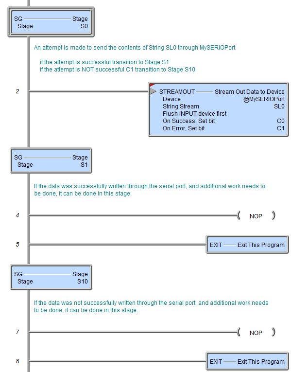
Rung Example: