Topic: DMD0251

Memory Configuration
The Memory Configuration section is used to manage all aspects of the memory allocation in the Do-more CPU. The memory configuration of the PC is integral to the system configuration which means that any change to the memory configuration CANNOT be downloaded to the CPU while it is in RUN mode; the PLC must be placed in Program mode while the new memory configuration is downloaded.
The three values across the top the page are Current Size (the amount of memory consumed by the current memory allocation scheme), Max Size (the maximum size available bases on the selected CPU), and the Space Available ( the space that remains for additional memory blocks, heap items and user data types). The PLC's memory configuration is managed by the three tabbed sections, one for each of the three major groups:
Memory Blocks
These are arrays of elements or structures, all of which are the same type and size. Memory block elements are referenced by the block's name and it's offset from the beginning of the block, which can be a constant or a variable value. There are two types of memory blocks: Built-in (which are automatically created in each Do-more Designer project) and User (which have been manually created). The size of the Built-in memory blocks can be changed, but they cannot be deleted. User blocks can be added and deleted as needed.
User-defined memory blocks must be created in the memory configuration utility before they can be used in a Do-more Designer project. The work of creating new memory blocks, deleting unused memory blocks, changing the size of existing memory blocks, and changing the retentive memory settings of memory blocks is done on the Memory Blocks tab.
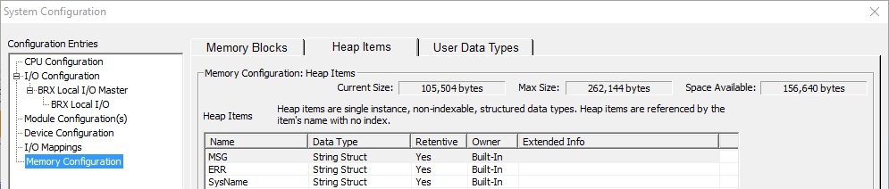
Heap Items
These are individual data structures that are not indexed. Heap items are referenced by their name only. There are three types of Heap Items: Built-in (which are automatically created for in each Do-more Designer project and are always present in the project), System (which are automatically created as part of the project any time the PLC requires them), and User (which have been manually created as programming elements that require them are added to the project). System and built-in heap items cannot be deleted; user heap items can be added and deleted as needed.
User-defined heap items can be created during an ladder logic editing session, but doing so will prevent the project from being downloaded to the PLC while the PLC is in RUN mode. The work of creating new heap items or blocks of heap items, deleting unused heap items, and changing the retentive memory settings of heap items is done on the Heap Items tab.
User Data Types
These are user-created definitions for data structures. User data types and the structures created with them are used to combine various data types into a single unit. Once the user data types have been created they will be used just like the system-created structure types, meaning that you use them to create new heap items (if you need single instances of a structure), or new memory blocks of them (if you need multiple instances of a structure). A user data type can be a maximum of 64 DWords in length, and can contain up to 255 individual fields.
The work of creating new user data types, deleting unused user data types, and changing the layout of existing user data types is done on the User Data Types tab.
Modbus Memory Blocks
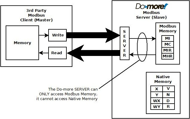
One part of the overall security system is preventing external devices (operator panels, HMIs, etc.) from being able to directly control the PLC's I/O and memory. When operating as a Modbus Server (Slave) - either Modbus/TCP or Modbus/RTU - the Do-more controller does not allow external devices that communicate through the Modbus protocol to have direct access to the controller's internal memory and I/O.
All Modbus Read and Write requests from external devices will be serviced from the four built-in memory blocks that are reserved for use by the Do-more controller's Modbus Server (Slave) device, they are: MC (Modbus Coils), MI (Modbus Inputs), MHR (Modbus Holding Registers), and MIR (Modbus Input Registers). The Modbus Server only has access to the MI, MC, MIR, and MHR memory blocks in the controller, it cannot access the other (native) memory blocks or the I/O in the controller.
The ladder logic instructions have access to all of the native memory AND the Modbus memory, so the Modbus memory locations can be referenced in place by the instructions. If data in the Modbus memory locations need to be converted (for example if it has to be byte-swapped, or converted to floating point) before it can be used, the Subscribe - Translate to Do-more instruction can be used to convert the data and store the converted data in Native memory, and the Publish - Convert from Do-more instruction can be used to convert data from native memory locations as required and store the converted values in Modbus memory.
The default configuration of the four blocks of Modbus memory has 1024 elements for the BIT ranges and 2048 elements for the numeric range elements, using decimal addressing, so there is no mapping of the Modbus memory required for the external read and write requests. The size of these ranges can be increased if needed.
As stated above, when operating as a Modbus Client, using the MRX - Modbus Network Read and MWX - Modbus Network Write instructions have access to all of the native memory as well as the Modbus memory. And while it is possible to use the MC, MI, MHR, MIR memory locations as destination registers for MRX instructions, and as source registers for MWX instructions, in most cases it is not advisable to do so because that memory is reserved for use by the Modbus Server.

DirectLOGIC Memory Blocks
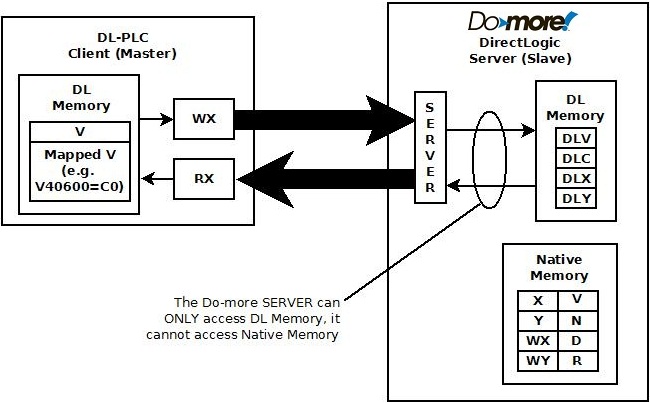
The same security system is in place when the Do-more controller is operating as a DirectLOGIC Server (Slave) meaning that it does not allow external devices that communicate through the K-Sequence protocol, or communication modules that work with DL processors - like the ERM and ECOM modules - to have direct access to the controller's internal memory and I/O.
All K-Sequence Read and Write requests from external devices, or backplane data requests from an ERM or ECOM will be serviced from the four built-in memory blocks that are reserved for use by the Do-more controller's DirectLOGIC Server (Slave) device, they are: DLC (Coils), DLX (Inputs), DLY (Outputs), DLV (Registers). The DirectLOGIC Server only has access to the DLC, DLX, DLY, and DLV memory blocks in the controller, it cannot access the other (native) memory blocks or the I/O in the controller.
The ladder logic instructions have access to all of the native memory AND the DirectLOGIC, so the DirectLOGIC memory locations can be referenced in place by the instructions. If data in the DirectLOGIC memory locations needs to be converted (for example if it has to be byte-swapped, or converted from BCD) before it can be used, the Subscribe - Translate to Do-more instruction can be used to convert the data and store the converted data in Native memory, and the Publish - Convert from Do-more instruction can be used to convert data from native memory locations as required and store the converted values in DirectLOGIC memory.
The default configuration of the four blocks of DirectLOGIC memory has 512 elements for the BIT ranges and 2048 elements for the numeric range, using octal addressing, so there is no mapping of the DirectLOGIC memory required for the external read and write requests. The size of these ranges can be increased if needed.
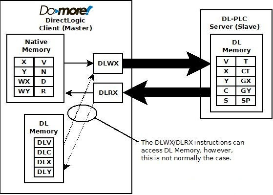
As stated above, when operating as a DirectLOGIC Client, using the DLRX - DirectLOGIC Network Read and DLWX - DirectLOGIC Network Write instructions have access to all of the native memory as well as the DirectLOGIC memory. And while it is possible to use the DLX, DLY, DLC, and DLV memory locations as destination registers for DLRX instructions, and as source registers for DLWX instructions, in most cases it is not advisable to do so because that memory is reserved for use by the DirectLOGIC Server.
See Also:
Memory View is used to edit and / or monitor the contents of Memory Blocks.
Memory Image Manager is used save a copy of the contents of the retentive memory locations and heap items in the offline Do-more Designer project.
Related Topics: