Topic: DMD0374

Ethernet I/O Master Configuration
Do-more CPUs that are equipped with an on-board Ethernet port can be configured to use that Ethernet port, or add a BX-P-ECOMEX (secondary Ethernet Adapter) to expand the I/O in a Do-more system. The Ethernet I/O Master function uses TCP/IP protocol used to communicate between the selected Ethernet Master port and its Ethernet-connected I/O slaves.
As much as possible, the Ethernet I/O Master handles Ethernet slave I/O in the same way it handles the local I/O. When the CPU is in PROGRAM (STOP) mode, the input module status is read from the slaves and updated in the CPU's memory, just like it is local input module status. When the CPU is in RUN mode status is read from the input modules in the slaves and updated in the CPU's memory, and output data from the CPU's memory is written to each of the output modules in the slaves; again, just like it is for local input module and output modules.
After an Ethernet I/O Slave has been added, there are three additional settings the Master can be configured to take when it encounters an error from this I/O Slave (the possible I/O Slave errors are listed here):
CPU remains in RUN mode on slave error selects what action to take if the CPU is in RUN mode and this I/O Slave reports an error:
If checked the CPU will remain in RUN mode.
If unchecked (default) the CPU will drop into PROGRAM mode.
The Slave must be online to enter RUN mode specifies whether or not the CPU can go to RUN mode based on whether or not this I/O Slave is present on the network.
If checked (default) the CPU can only go to RUN mode if this I/O Slave is present on the network.
If unchecked the CPU can go to RUN mode even if this I/O Slave is NOT present on the network.
On slave error, inputs will ... selects what action to take with the current image register data for the discrete and analog input modules in this I/O Slave if an error is reported:
- If Hold last state (default) is selected the image register data for all of the discrete inputs and all of the analog inputs will retain the last values that were received.
- If Be cleared is selected the image register data for all discrete inputs will set to OFF, and the image register data for analog inputs will be set to 0.
Minimize Competing Network Traffic
As stated before, the Ethernet I/O Master tries to handle Ethernet slave I/O with the same degree of importance as it does the local I/O. To this end, The Ethernet I/O process tries to keep the Ethernet slave I/O in sync with the local I/O. This can result in a very high volume of network traffic between the Ethernet I/O Master and it's I/O Slaves. For this reason, take note of the following recommendations:
On BRX PLCs, adding an BX-P-ECOMEX (Secondary Ethernet Adapter POM) allows Ethernet-capable instructions like Send Email (EMAIL) to use either the on-board port or the BX-P-ECOMEX. Doing this leaves only the Ethernet I/O Master's traffic on the other Ethernet port. In DL205 systems which can only target the on-board Ethernet port (not an ECOM100 module), these instructions should be used as sparingly as possible.
The Ethernet Master I/O network (either the on-board Ethernet port or the BX-P-ECOMEX and all of the Ethernet I/O Slaves) should be on an isolated network. The goal of having the Ethernet I/O Master operating on an isolated network is that it allows the Ethernet I/O update rate to be as fast and as stable as possible. The aforementioned recommendations will minimize the volume of network traffic and the number of different types of network packets that appear on the network, which will allow the Ethernet port to concentrate on processing read and write requests for the Ethernet I/O Master.
Functions like the Modbus/TCP Server, the EtherNet/IP Server and TimeSync that are exclusive to the on-board Ethernet port should be disabled if they are not being used.
External devices that require the Do-more CPU to provide Ethernet server connectivity - such as Do-more Designer, C-More panels, or other HMI devices - can be connected by adding an ECOM100 module in DL205 systems, or a BX-P-ECOMLT, or BX-P-ECOMEX in BRX systems.
Ethernet-capable instructions such as DLRX - DirectLOGIC Network Read, DLWX - DirectLOGIC Network Write etc. can be configured to use an ECOM100 module in DL205 systems, or a BX-P-ECOMEX in BRX systems.
While it is true that the on-board Ethernet port of the CPU and / or the BX-P-ECOMEX can be configured to perform all of the aforementioned functions concurrently with the Ethernet I/O Master, having it do so can result in instability and / or poor performance which can show up as increased scan time, scan times with wide variations, slow update rates for all of the operations that use the Ethernet port, or Ethernet I/O Slaves that timeout which will cause the CPU to fall out of RUN mode.
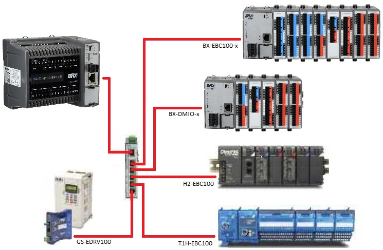
Supported I/O Slave Controllers
Ethernet I/O Slaves can be any combination of up to 16 BX-DMIO-x, BX-EBC100-x, H2-EBC100, T1H-EBC100, or GS-EDRV100.
These following non-Do-more devices require the following minimum
firmware versions to be used as Ethernet
I/O Slaves for a Do-more CPU. If any of your devices need a firmware update to make them useful for Ethernet I/O Slaves, use the Live
Update feature of NetEdit 3 to download the needed firmware files and apply the
required updates to these devices:
H2-EBC100 must be firmware v4.0.593 or greater
Refer to Chapter 4 of the Do-more H2 Series PLC Hardware User Manual for any module placement restrictions and power budget calculations.
T1H-EBC100 must be firmware v4.0.1393 or greater.
Because the Terminator I/O systems do not have fixed-size I/O bases, refer to Chapter 4 of the Do-more T1H Series PLC Hardware User Manual for any module placement restrictions, and for base arrangements using multiple power supplies to deal with power budget issues.
GS-EDRV100 must be firmware version v5.0.229 or greater.
Note: the 10-Base-T equivalents of the above modules (H2-EBCs, H4-EBCs, and GS-EDRVs) can NOT be used as Ethernet I/O Slaves; the only way these legacy modules can be used in a Do-more system is if they are Remote I/O slaves for an H2-ERM module.
Supported I/O Modules
All of the discrete and analog I/O modules that are supported in the Do-more's local base can be used as I/O in the Slave bases. Additionally, the H2-CTRIO, H2-CTRIO2, and T1H-CTRIO modules are also supported as I/O in the Slave bases. Communication modules (SERIO, ERM, and ECOM) modules are NOT supported in the remote bases.
After the Ethernet I/O Master is configured and running, the Ethernet I/O Monitor can be used to display the "health" of the currently configured network of Ethernet I/O Slaves.
Configuring the Ethernet I/O Master
Select Enable Ethernet I/O Master then check the Enable Ethernet I/O Master option - or click the Enable Ethernet I/O Master selection in the I/O pane of the Dashboard. Enabling this option is the first of the two steps required to properly configure the Ethernet I/O Master. This selection only enables and disables the Ethernet I/O Master function, it does not select the I/O Slaves, nor does it configure those Slaves.
Note: in versions previous to 2.7 this selection was enabled on the CPU Configuration page.
Note: this option was not available in the original release of the Do-more products. If this option is grayed out on the CPU Configuration page it indicates that the current Do-more CPU firmware does not support this function. Do-more Designer v1.1.0 or greater and Do-more CPU firmware v1.1.0 or greater are required to support this function. Use the Check for Updates feature of Do-more Designer to download any required updates.
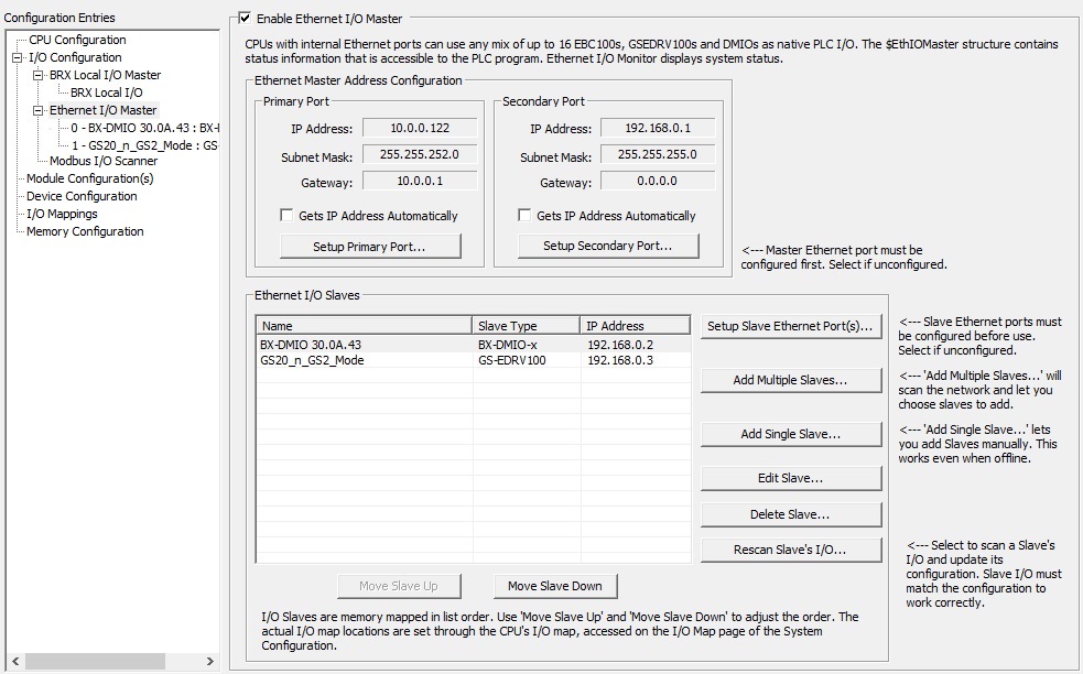
The Ethernet Master Address Configuration section displays the current TCP/IP network configuration of the on-board Ethernet port and a BX-P-ECOMEX Secondary Ethernet Port POM (if it exists). Both Ethernet ports must be configured with at least a valid TCP/IP address and Subnet Mask before either can be used by the Ethernet I/O Master function.
IP Address, Subnet Mask, and Gateway entries are the TCP/IP address, Subnet Mask, and Network Gateway of the on-board Ethernet port and BX-P-ECOMEX respectively.
Gets IP Address Automatically will be unchecked if the TCP/IP addressing is statically assigned; it will be checked if the port is getting its TCP/IP addressing from a DHCP Server.
Click the Setup Primary Port or Setup Secondary Port buttons to change the static configuration of the respective ports.
The At startup, Override PLC's Wait Time for Slaves: option allows the user to specify the amount of time (in seconds) the CPU will wait for configured Ethernet Remote I/O slaves to get themselves powered up and be accessible on the network. The default wait time of 15 seconds is typically more than enough for an EBC100 or a DMIO, but may not be enough for a GS-EDRV100 which must get its serial connection to the GS drive established before it allows the Ethernet connection to be properly setup. The default setting is 15 seconds; this wait time can be shortened by entering a value between 1 and 15, or lengthened up to a maximum of 255 seconds.
Setup Slave Ethernet Port(s) is used to configure the TCP/IP network parameters for the DMIO, EBC100 and EDRV100 devices that will be used as Ethernet I/O Slaves. Each DMIO, EBC100 and EDRV100 devices must be configured with a valid TCP/IP address and Subnet Mask before it can be used as an I/O Slaves by the Ethernet I/O Master. When the Setup Slave IP Configuration dialog is opened it queries the selected network adapter for any Ethernet devices that can potentially be Ethernet I/O Slaves. All devices that are found on that adapter's network will be displayed in the list.
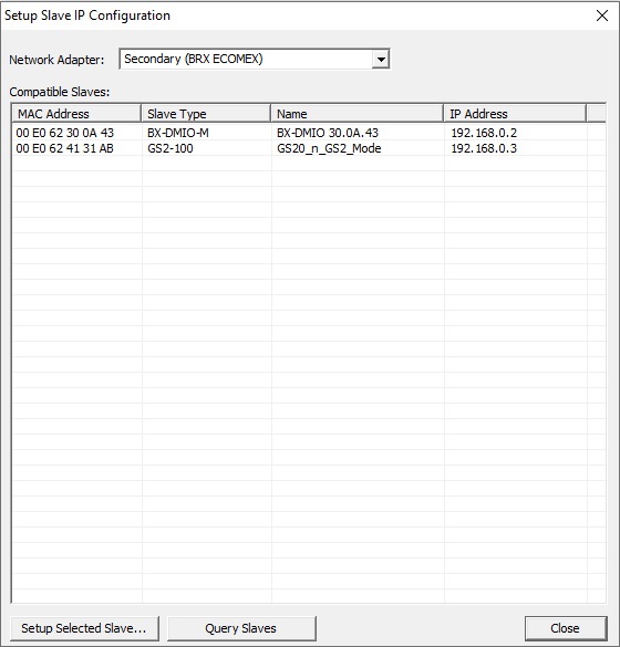
Selecting a different Network Adapter will run the query operation on that adapter:
Default means the TCP stack will route the packets to the first Ethernet port that can process the packet; on CPUs without a Secondary port (BX-P-ECOMEX) this will always be the on-board port. This is also the proper selection for backwards compatibility with previous Do-more Technology versions and with H2-DM1E and T1H-DM1E CPUs because they have no provision for a Secondary Ethernet port.
Primary (Internal Ethernet) will send packets through the on-board Ethernet port of the Do-more CPU.
Secondary (BRX ECOMEX) will send packets through the BRX CPU's secondary Ethernet port (BX-P-ECOMEX) if one is installed.
Click the Query Slaves button to manually perform the query again. After all of the Slaves have been configured, click the Close button to return to the main configuration dialog.
If you need to changed the current configuration of one of the devices in the list, highlight the device in the list and click the Setup Selected Slave... button to open a dialog that will allow the TCP/IP Networking parameters to be changed for that device.
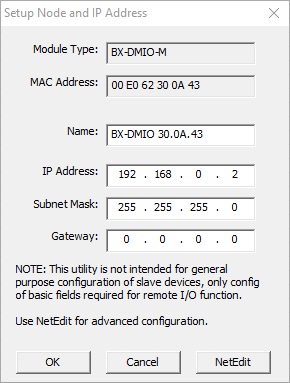
Name sets the name to any 255 character combination of alphanumeric and punctuation characters. IP Address, Subnet Mask, and Gatewayentries set the TCP/IP address, Subnet Mask and Network Gateway address of the device's Ethernet port respectively.
Click OK to close the dialog and save any changes that were made, click Cancel to close the dialog and discard any changes that were made, or Click NetEdit to launch the NetEdit utility.
Add Multiple Slaves uses an Ethernet broadcast to locate compatible Ethernet devices that are on the network of the selected Network Adapter.
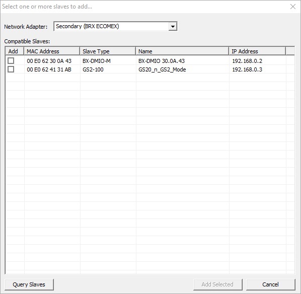
After the query is complete this dialog will present a list of the compatible devices. A total of 16 compatible devices of any mix of the following list of compatible Ethernet device can be added as Ethernet I/O Slaves:
BX-DMIO-x (BRX Do-more I/O Controller)
BX-EBC100-x (BRX Ethernet Base Controller)
H2-EBC100 (DL205 Ethernet Base Controller) with firmware v4.0.583 or greater.
T1H-EBC100 (Terminator Ethernet Base Controller) with firmware v4.0.1390 or greater. Note: the Hot-Swap feature in the T1H-EBC100 is NOT supported, if a module in the base with the T1H-EBC100 is removed or added while the CPU is in RUN mode, the CPU will drop out of RUN mode.
GS-EDRV100 (GS Series Drive Ethernet interface) with firmware v5.0.226 or greater. Supported GS drives are the GS1, GS2, DURA Pulse-GS3, DURA Pulse-GS4, and GS20 (in GS2 mode).
10Base-T versions of the above devices (H2-EBCs, H4-EBCs, and GS-EDRVs ) cannot be used as Ethernet I/O Slaves.
Note: If there are no devices in the list, or a device you know is on the network is not in the list, make sure the Slave devices have the minimum firmware version that is required to work as an Ethernet I/O Slave. Use the Live Update feature of NetEdit 3 to download any needed firmware files and apply any required firmware updates to these units to make them compatible. Also make sure the TCP/IP address assigned to the on-board port - or the BP-P-ECOMEX - and to the I/O Slaves place them all on the same IP network. Click Query Slaves to perform the broadcast query again.
Selecting a different Network Adapter will run the query operation on that adapter:
Default means the TCP stack will route the packets to the first Ethernet port that can process the packet; on CPUs without a Secondary port (BX-P-ECOMEX) this will always be the on-board port. This is also the proper selection for backwards compatibility with previous Do-more Technology versions and with H2-DM1E and T1H-DM1E CPUs because they have no provision for a Secondary Ethernet port.
Primary (Internal Ethernet) will send packets through the on-board Ethernet port of the Do-more CPU.
Secondary (BRX ECOMEX) will send packets through the BRX CPU's secondary Ethernet port (BX-P-ECOMEX) if one is installed.
Click the box in the Add column to the left of each compatible Slave device to add to the configuration then click Add Selected to save the selections and close the dialog. Click Cancel to close the dialog and discard any selections that were made.
Add Single Slave... will open a dialog that allows a slave to be added to the configuration that is not currently accessible with the Ethernet Query mentioned above.
Note: this selection only adds the Slave device to the configuration, it does NOT add any I/O modules for that Slave; the I/O modules for each slot must also be added manually. Adding I/O modules is done by expanding the Ethernet I/O Master, selecting the Slave that was manually added, then right-click on each slot in the DL205 base and selecting the appropriate I/O module for that slot. This process is discussed in detail in the How to Manually Add an I/O Module section below.
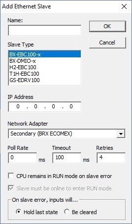
The first three items uniquely identify the Slave on the network, and describe the communication requirements. Name specifies the name of the slave (any 255 character combination of alphanumeric and punctuation characters), the Slave Type selects the type of device from the list (BX-DMIO-x, BX-EBC100-x, H2-EBC100, T1H-EBC100, or GS-EDRV100), and the IP Address specifies the TCP/IP address of the slave device.
The Network Adapter selection specifies the Ethernet connection to the network where the Slave resides:
Selecting Default means the TCP stack will route the packets to the first Ethernet port that can process the packet; on CPUs without a Secondary port (BX-P-ECOMEX) this will always be the on-board port. This is also the proper selection for backwards compatibility with previous Do-more Technology versions and with H2-DM1E and T1H-DM1E CPUs because they have no provision for a Secondary Ethernet port.
Select Primary (Internal Ethernet) if the Slave is on the same network as the on-board Ethernet port of the Do-more CPU.
Select Secondary (BRX ECOMEX) if the Slave is on the same network as the BRX CPU's secondary Ethernet port (BX-P-ECOMEX).
The next three items describe the communication requirements. All of the Slaves have an Ethernet Watchdog Timer that gets set when the Ethernet I/O Master initializes the Slave. The value of this timer is computed from the Poll Rate, Timeout and Retries settings for the Slave using the following formula: Poll Rate + (Timeout * (Retries +1)). If the Ethernet communication between the Ethernet I/O Master and this Slave is ever interrupted longer than the timer value the Slave will turn OFF all of the discrete outputs and set all of the analog output values to 0.
Poll Rate specifies the frequency (in milliseconds) at which the Ethernet I/O Master will read and write to the I/O modules in this slave device. This can be any value between 0 and 32767. The default value of 0 means as "often as possible".
Timeout specifies the amount of time (in milliseconds) the Ethernet I/O Master will wait on a response from a read or write operation before it retries that operation. This can be any value between 25 and 32767.
Retries specifies the number of times the Ethernet I/O Master will retry a read or write operation before it cancels that operation and returns an error. This can be any value between 25 and 32767.
The last three options specify what actions the Ethernet I/O Master will take when it encounters an error from this I/O Slave (the possible I/O Slave errors are listed here):
CPU remains in RUN mode on slave error selects what action to take if the CPU is in RUN mode and this I/O Slave reports an error:
If checked the CPU will remain in RUN mode.
If unchecked (default) the CPU will drop into PROGRAM mode.
The Slave must be online to enter RUN mode specifies whether or not the CPU can go to RUN mode based on whether or not this I/O Slave is present on the network.
If checked (default) the CPU can only go to RUN mode if this I/O Slave is present on the network.
If unchecked the CPU can go to RUN mode even if this I/O Slave is NOT present on the network.
On slave error, inputs will ... selects what action to take with the current image register data for the discrete and analog input modules in this I/O Slave if an error is reported:
- If Hold last state (default) is selected the image register data for all of the discrete inputs and all of the analog inputs will retain the last values that were received.
- If Be cleared is selected the image register data for all discrete inputs will set to OFF, and the image register data for analog inputs will be set to 0.
After an I/O Slave has been added to the configuration, the next five buttons are used to change that configuration:
Edit Slave... will open a dialog similar to the above to change the highlighted slave's configuration. The same options are available as in the Add Ethernet Slave dialog discussed above.
Delete Slave... will remove the highlighted slave and all of its bases, I/O modules, and I/O Mapping information from the current System Configuration.
Note: any module configurations for Modules in the bases will be Disconnected. Any instructions in the ladder logic program that reference I/O modules that were removed will remain associated with the disconnected module configurations. Disconnected module configurations can be associated with other I/O modules by reassigning the configuration to a compatible module though the Assign Config function on the Module Configuration page.
Rescan Slave's I/O... will re-read the I/O modules from the highlighted slave and refresh that list of I/O modules.
Note: the number, type and position of the I/O Modules in the base determines the address mapping of those I/O modules. If the Rescan operation finds additional I/O modules, or if the Rescan can no longer find I/O modules that were previously there, this will cause the address mapping to change for this Slave and for every Slave that follows it in the list of Ethernet Slaves. The default I/O address mapping information can be viewed and changed on the I/O Mappings page.
Move Up / Move Down will reposition the currently highlighted Slave one position closer to the top, or one position closer to the bottom of the list of slaves respectively.
Note: the I/O Mapping for the modules in the slaves begins where the I/O Mapping for modules in the local base ends. This means the position of the Slaves in the list determines the address mapping of the I/O modules. Moving a Slave up or down in the list will cause the address mapping to change for every Slave that follows the one being moved. The default I/O address mapping information can be viewed and changed on the I/O Mappings page.
Error Reporting:
The Ethernet I/O Master can manage any mix of up to 16 Ethernet I/O Slaves. The $EthIOMaster contains member fields that report the configuration status for each of the Slaves and report errors and warnings for each slot that contains an I/O module. The Ethernet I/O Master classifies Errors as any condition that will prevent the CPU from going to RUN mode; Warnings are conditions that allow the CPU to go RUN mode but an I/O module is reporting an issue that may require user intervention to resolve.
The Ethernet I/O Monitor is another utility that shows the current "health" of the Ethernet I/O Master and its configured Ethernet I/O Slaves.
The I/O System View will display all of the current Error and Warning information for all of the I/O modules in all of the Ethernet I/O Slaves.
The Do-more CPU has several built-in Bit and Word locations that can be utilized at runtime to detect Errors and Warnings in the Ethernet I/O subsystem. Refer to the following Data View to see the progression of error reporting that can be utilized in the ladder logic project:
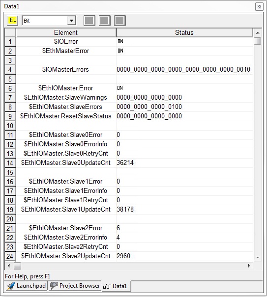
There is an I/O Error ($IOError is ON).
The I/O Master that is reporting the error is Ethernet I/O Master (bit 1 of IOMasterErrors is ON).
The Ethernet I/O Slave that is causing the Error (Slave #2) is indicated in the $EthIOMaster.SlaveErrors structure member. With the .SlaveErrors structure member viewed in a Binary form, each Bit represents one of the 16 possible I/O Slaves, the lowest order Bit being Slave 0, the highest order Bit being Slave 15.
For each of the 16 potential I/O Slaves, there are two structure members that contain an error code that explains the problem and the slot number of the I/O module that is involved. The structure members are named .Slave0Error & .Slave0ErrorInfo through .Slave15Error & .Slave15ErrorInfo. In the example above, Slave #2 is reporting an error code 6 (I/O Mismatch) in Slot #4.
The following table lists the range of potential Error codes that can appear in the .Slave0Error through .Slave15Error fields:
Clearing Ethernet I/O Slave Errors and Warnings
If any of the Ethernet I/O Slaves reports an I/O Warning, like a "broken transmitter" or "drive tripped" the remote slave will retain that warning until it is manually cleared. It does this to make sure that all of error and warning conditions that occur at any slave - specifically any intermittent ones - will be reported to the Ethernet I/O Master. So, after the problem that is causing the Error or Warning condition is resolved, there are two methods available to manually clear the retained status data from the Ethernet I/O system:
Using Do-more Designer: opening the I/O System View will reset the Error and Warning information in each slave device when it polls each slave device for its Error and Warning data.
Runtime in Ladder Logic: in Do-more version 2.0 and later, the $EthIOMaster structure has a 16-Bit field named .ResetSlaveStatus. Each slave device is mapped to a bit in that 16-Bit register as follows: Bit 0 = Slave 0, Bit 1 = Slave 1, ... Bit 15 = Slave 15. Setting a Bit to a value of 1 will cause the Ethernet I/O Master to clear the retained the Error and Warning data in the corresponding slave device and then set that Bit back to 0.
The preferred method for doing this at runtime is to perform a one-time copy of the contents of $EthIOMaster.SlaveErrors to $EthIOMaster.ResetSlaveStatus.
![]()
This will cause the Ethernet I/O Master to issue the reset command to each slave device that is currently showing an error. Each slave device that no longer has any error or warning data will leave its corresponding bit in $EthIOMaster.SlaveErrors at 0. Any slave device that still has Error or Warning data will have it corresponding bit in $EthIOMaster.SlaveErrors set back to 1.
Ethernet Master I/O Startup and Shutdown Sequences
Once the Ethernet Master I/O configuration has been set the Do-more CPU will perform the following sequences depending on the starting condition. Again, it is important to understand that the CPU places the same importance on the Ethernet Master I/O that it does on the Local I/O Master. The Ethernet I/O Master configuration must remain consistent for the CPU to operate normally.
Power ON Initialization Sequence is executed each time the CPU is powered ON.
-
Query Network to make sure the currently configured Slaves are present on the network.
-
If all Slaves are present, each Slave is then queried to make sure that the I/O modules that are currently found in each Slave match the I/O modules that are in the stored configuration.
-
If all of the I/O modules match the current configuration the Ethernet Master will download the module configuration for all of the I/O modules that have one, for example, the CTRIO module.
The ERR LED (BX-DM1E, H2-DM1E) or STAT LED (T1H-DM1E) will be rapidly blinking RED while the module configurations are being downloaded.
-
If all of the module configurations are downloaded successfully the initialization process is complete.
-
A unique value (called the Link Monitor) is written to each I/O Slave. This unique Link Monitor value is included as part of each data packet between the Master and its I/O Slaves. This allows the Ethernet I/O Master to verify that each response packet is from one of its own I/O Slaves, and each I/O Slave can know that each data packet it receives is from its own Master.
-
At this point the Ethernet I/O Master will begin normal updates for the I/O modules in all of its I/O Slaves as described in the section below.
-
If any of the Module configurations fail to download the CPU will NOT go into RUN mode until the problem is resolved
The ERR LED (BX-DM1E, H2-DM1E) or STAT LED (T1H-DM1E) will be solid RED.
The system Bit $IOError (ST152) - "One or more I/O Master are reporting a problem with a module" will be ON. The error message can be seen on the System Status tab of the System Info utility.
The corresponding Bit for each Slave that is reporting a module error will be ON in the system structure member $EthIOMaster.SlaveError.
The appropriate structure member ($EthIOMaster.Slave0ErrorInfo - $EthIOMaster.Slave7ErrorInfo) will contain the number of the first slot that has an I/O module that failed to download its Module configuration.
-
If one or more of the I/O modules is different than what is in the configuration (this could be a module that is missing or a module that is a different type), the CPU will NOT go into RUN mode until the problem is resolved.
The ERR LED (BX-DM1E, H2-DM1E) or STAT LED (T1H-DM1E) will be solid RED.
The system Bit $IOError (ST152) - "One or more I/O Master are reporting a problem with a module" will be ON. The error message can be seen on the System Status tab of the System Info utility.
The corresponding Bit for each Slave that is reporting a module error will be ON in the system structure member $EthIOMaster.SlaveError.
The appropriate structure member ($EthIOMaster.Slave0ErrorInfo - $EthIOMaster.Slave7ErrorInfo) will contain the number of the first slot that has an I/O module that is different than the configuration.
-
If one or more of the Slave devices (that are configured as required to be present on the network) are NOT present on the network, the CPU will NOT go into RUN mode until the problems is resolved.
The ERR LED (BX-DM1E, H2-DM1E) or STAT LED (T1H-DM1E) will be solid RED.
The system Bit $IOError (ST152) - "One or more I/O Masters are reporting a problem with a module" will be ON.
The system Bit $EthMasterError (ST153) - "The Ethernet I/O Master is reporting an error, most likely a slave is offline" will be ON. These error messages can be seen on the System Status tab of the System Info utility.
The corresponding Bit for each Slave that is NOT present will be ON in the system structure member $EthIOMaster.SlaveErrors.
The Ethernet I/O Master will continue to query the network for missing Slaves at 10 second intervals. If one of the missing Slaves appears on the network, it will be initialized as described above.
After all of the missing Slaves are located the remainder of the initialization process will run, if that process completes successfully the ERR LED (BX-DM1E, H2-DM1E) or STAT LED (T1H-DM1E) will go OFF and the CPU can then be manually put into to RUN mode.
PROGRAM mode - to- RUN mode Sequence is executed each time the CPU transitions from PROGRAM mode to RUN mode. The process is very similar to the power-on sequence but there are a couple of notable exceptions that are described below. The resolution to any problems is the same as described in the power-on sequence.
Query Network to make sure the currently configured Slaves are still present on the network.
If all Slaves are present, each Slave is then queried to make sure that the I/O modules that are currently found in each Slave match the I/O modules that are in the stored configuration.
If all of the I/O modules match the stored configuration the Ethernet Master will initialize the image register locations with the Module configuration data for any that require it, for example: the Terminator I/O analog output modules, and the F2-8AD4DA-x modules. The Module configurations for all I/O modules are NOT downloaded again, only image register locations that need to be initialized with Module configuration data get processed.
After all of the initialization is complete the Ethernet I/O Master will begin normal updates for the I/O modules in its I/O Slaves as described in the section below.
If one or more of the I/O modules is different than what is in the configuration (this could be a module that is missing or a module that is a different type), the CPU will NOT go into RUN mode until the problems is resolved.
If one or more of the configured Slaves is NOT present on the network, the CPU will NOT go into RUN mode until the problems is resolved.
RUN mode -to- PROGRAM mode is executed each time the CPU transitions from RUN mode to PROGRAM mode.
All of the discrete outputs are turned OFF and a value of 0 is written to all of the channels of the analog output modules.
Ethernet Master I/O Update Cycle
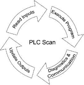
Once it has been enabled and its Slaves configured, the CPU allows the Ethernet I/O Master to run during the Diagnostics and Communication slice of each scan. Each time the Ethernet I/O Master function is allowed to run it will update all of the inputs and outputs on all of the configured I/O slaves.
When the CPU is in PROGRAM mode, only status data from the input modules in each I/O Slave is read. That data is then used to update the Do-more's local copy in the image register. Any I/O modules that have structures instead of I/O, the structures will be read and the image register will be updated with that data. This allows both the input modules from Ethernet I/O Slaves and input modules in the local base to continue to update in PROGRAM mode.
When the CPU is in RUN mode, data for each output module is sent to the appropriate I/O Slave, and for I/O modules that have structures instead of I/O, the I/O modules will be updated with data from their structures. The status data from the input modules in each I/O Slave is read. Any I/O modules that have structures instead of I/O, the structures will be read and the image register will be updated with that data. The data from the input modules is then used to update the Do-more's local copy in the image register.
See Also:
EtherNet/IP Server / Adapter Configuration
Ethernet I/O Master Configuration
Modbus I/O Scanner Configuration
Related Topics:
Ethernet I/O Monitor will display the "health" of the currently configured network of Ethernet I/O Slaves