Topic: DMD0300

PEERLINK - Share Data w / PLCs
The Share Data w / PLCs (PEERLINK) instruction is used to join a data sharing network that consists of other Do-more CPUs (BX-DM1E, H2-DM1E, T1H-DM1E) or a DirectLOGIC PLC system using an H2-ECOM100 module. Each member of the data sharing network receives data from all of the other Do-more CPUs and ECOM100s on that data sharing network. Each member can optionally send data to the other members of the data sharing network by electing to "publish" one or more blocks of PEERLINK (PL) memory.
The PEERLINK instruction uses TCP/IP broadcast packets to publish the blocks of data to the network. One caveat with the use of broadcast packets
is that it does limit the scope of the shared data network to the local broadcast domain![]() A broadcast domain is a logical network segment in which any device connected to the network can directly transmit to any other on the domain without having to go through a routing device. These are typically very basic networks that use hubs rather than switches or routers. A special broadcast address consisting of all 1s is used to send frames to all devices on the network.. Even though the PEERLINK instruction uses broadcast packets, the on-board
Ethernet port still needs to be configured with a TCP/IP address and Subnet
Mask that is unique on the local network.
A broadcast domain is a logical network segment in which any device connected to the network can directly transmit to any other on the domain without having to go through a routing device. These are typically very basic networks that use hubs rather than switches or routers. A special broadcast address consisting of all 1s is used to send frames to all devices on the network.. Even though the PEERLINK instruction uses broadcast packets, the on-board
Ethernet port still needs to be configured with a TCP/IP address and Subnet
Mask that is unique on the local network.
There can only be one PEERLINK instruction in a Do-more Designer project and the instruction must be in the $Main code-block. This effectively means that a single Do-more CPU can only be part of one data sharing network.
The PEERLINK instruction works with a predefined section of memory named PL. The PL memory contains 256 locations named PL0 through PL255. These 256 locations are divided into 16 blocks. Each of these 16 data blocks consists of 16-Bit unsigned registers. These blocks provide the local storage for the data that is sent and received over the data-sharing network. In addition to the data blocks, PL memory contains entries for some Bits and Words that are available for use in a ladder program to monitor the runtime status of the PEERLINK network, and to optionally control the updates to individual PEERLINK blocks.
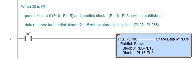
When the input logic to the PEERLINK instruction is ON (the instruction is enabled), at a rate of 10 times per second, the instruction will publish all of the blocks that it is configured to publish, and will process any PEERLINK data blocks that it receives. When the input logic is OFF, (the instruction is disabled), it DOES NOT publish any of its blocks and DOES NOT process any PEERLINK data blocks that it receives.
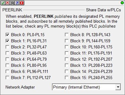
Network Adapter: because this instruction uses Ethernet broadcasts to send packets, you must select which of the Ethernet ports to send packets through:
Default means the TCP stack will route the packets to the first Ethernet port that can process the packet; on CPUs without a Secondary port (BX-P-ECOMEX) this will always be the on-board port. This is also the proper selection for backwards compatibility with previous Do-more Technology versions and with H2-DM1E, T1H-DM1E, and BX-DM1 CPUs because they have no provision for a Secondary Ethernet port.
Primary (Internal Ethernet) will send packets through the on-board Ethernet port of the Do-more CPU.
Secondary (BRX ECOMEX) will send packets through the BRX CPU's secondary Ethernet port (BX-P-ECOMEX).
Publishing and Subscribing:
The Share Data w / PLCs (PEERLINK) instruction uses the verbs 'publishing' and 'subscribing' to describe how the CPU's data is exchanged with other CPUs and / or ECOM100s on the data sharing network.
Publishing is analogous to sending data, and is done only if the PEERLINK instruction is configured to 'publish' one or more of its own data blocks. If so configured, the Do-more CPU will broadcast a packet that contains the data from the selected PL memory blocks. There are sixteen unique data blocks, and each data block can only be published by one CPU. This means there can be a maximum of sixteen unique CPUs configured to publish blocks of data. A single Do-more CPU or ECOM100 can be configured so that it publishes none of the blocks, one block, some of the blocks, or even all 16 of the blocks.
Subscribing is analogous to receiving data, and is accomplished by 'subscribing to' the data blocks of all the other CPUs on the data sharing network. Once the PEERLINK instruction is enabled, it listens to the network for PEERLINK broadcasts messages from other Do-more CPUs or ECOM100s, and when it receives one, it takes the data from that packet and stores it in the designated block in the CPU's local PL memory.
Subscribing to the shared data network is a passive operation in that it only receives data from the network. Simply placing a PEERLINK instruction in the project will cause it to subscribe to all of the data blocks from all of the CPUs on the shared data network. Because the subscribing process always needs to run, the PEERLINK instruction must be placed in the $Main code-block (which is guaranteed to be running any time the Do-more CPU is in RUN mode).
Unlike publishing in which you select which specific blocks to publish, you cannot subscribe to individual data blocks. Because subscribing is a passive operation there can be a virtually unlimited number of Do-more PLCs and / or ECOM100s subscribing to the shared data blocks.
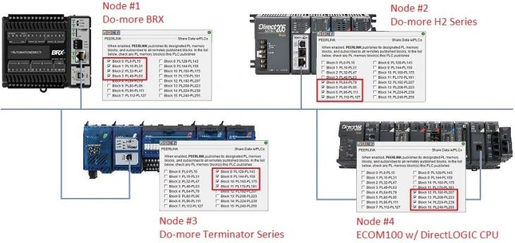
In the following graphic, the four Do-more systems are using PEERLINK instructions to participate in a data sharing network.
Node #1 is publishing Blocks 0 through 3, and subscribing to Blocks 4 through 15
Node #2 is publishing Blocks 4 through 7, and subscribing to Blocks 0 through 3 and Blocks 8 through 15
Node #3 is publishing Blocks 8 through 11, and subscribing to Blocks 0 through 7 and Blocks 12 through 15
Node #4 is publishing Blocks 12 through 15, and subscribing to Blocks 0 through 11
When the network is running all 16 blocks of PL memory in all four of the Do-more system will be synchronized.
Status Information:
The red triangle in the upper left corner indicates this is a Fully Asynchronous instruction.
The status information that is displayed in the PEERLINK instruction depends on the state of the input logic.
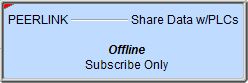
Offline indicates the input logic is OFF, or the CPU is in Program mode.

Subscribe Only indicates the instruction is configured to only receive data, it is NOT publishing any data.
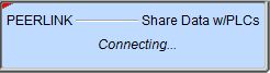
Connecting ... indicates the input logic is transitioning from OFF to ON, the PEERLINK instruction is gathering the status data for all the nodes
which typically takes one to two seconds.
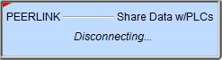
Disconnecting ... indicates the input logic is transitioning from ON to OFF, the PEERLINK instruction is closing the connections to the other nodes,
this typically takes one to two seconds.
Once the PEERLINK instruction is enabled and the network is functioning, each PLC will be sending and receiving data at an approximate rate of ten packets per second, so the transfer rate of a normally operating network should be in the range of 9 to 11 transfers per second.
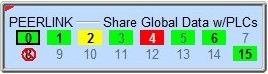
The status display uses the following background colors to quickly relate the quality (rate) of the communication between PLCs:
![]() Green Background indicates normal communication speed (receiving
eight or more packets per second). In the example above Blocks 0, 1, 3,
5, 6 & 15 are communicating normally.
Green Background indicates normal communication speed (receiving
eight or more packets per second). In the example above Blocks 0, 1, 3,
5, 6 & 15 are communicating normally.
![]() Yellow Background indicates slower than normal communication
rate, (receiving four to seven packets per second). In the example above
Block 2 is communicating slowly.
Yellow Background indicates slower than normal communication
rate, (receiving four to seven packets per second). In the example above
Block 2 is communicating slowly.
![]() Red Background indicates very slow communication rate, (receiving
fewer than three packets per second). In the example above Block 4 is
communicating very slowly or not at all.
Red Background indicates very slow communication rate, (receiving
fewer than three packets per second). In the example above Block 4 is
communicating very slowly or not at all.
![]() Normal Box Background (with Grayed Numeral) indicates that no CPU on the network is publishing that
particular block. In the example above Blocks 7, 9, 10, 11, 12, 13, and
14 are not being published.
Normal Box Background (with Grayed Numeral) indicates that no CPU on the network is publishing that
particular block. In the example above Blocks 7, 9, 10, 11, 12, 13, and
14 are not being published.
The PEERLINK instruction also uses combinations of the following attributes to display important status information for each of the blocks:
-
 Bold Box Outline indicates 'My Blocks',
that is, the blocks that this CPU is publishing. In the example
above Block 0 is being published by this PLC.
Bold Box Outline indicates 'My Blocks',
that is, the blocks that this CPU is publishing. In the example
above Block 0 is being published by this PLC.
-
 Green, Yellow, or Red background with Grayed
Numeral indicates that updates to the block have been inhibited,
in the example above Blocks 3 and 5 have their updates inhibited. The
inhibit bits for the blocks allow both the publisher and the subscribers
to control updates to the CPU's PEERLINK memory.
Green, Yellow, or Red background with Grayed
Numeral indicates that updates to the block have been inhibited,
in the example above Blocks 3 and 5 have their updates inhibited. The
inhibit bits for the blocks allow both the publisher and the subscribers
to control updates to the CPU's PEERLINK memory.
-
In the PLC that is publishing the block, setting the inhibit bit prevents that block from being published.
-
In the PLC that is subscribing to a block, setting the inhibit bit prevents that block from being updated in the CPU.
-
 Red Circle with a Slash indicates
a configuration error meaning there is a more than one CPU configured
to publish this block. In the example above Block 8 has a configuration
error.
Red Circle with a Slash indicates
a configuration error meaning there is a more than one CPU configured
to publish this block. In the example above Block 8 has a configuration
error.
Map of PEERLINK (PL) Memory:
The following table contains entries for all of the Bits and Words that are available for use in a ladder program to monitor the runtime status of the PEERLINK network and to optionally control the updates to individual PEERLINK blocks.
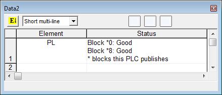
Data View Display Formats
Note: These formats are for display purposes only, the PEERLINK variables cannot be edited when displayed using any of the formats.
Short multi-line:
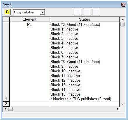
Long multi-line:
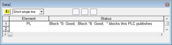
Short single line:
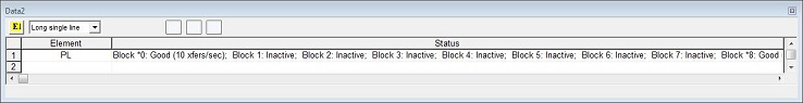
Longsingle line:
See Also:
RX - Do-more Network Read (Do-more PLC <-- Do-more PLC)
WX - Do-more Network Write (Do-more PLC --> Do-more PLC)
DLRX - DirectLOGIC Network Read (Do-more PLC <-- DirectLOGIC PLC)
DLWX - DirectLOGIC Network Write (Do-more PLC --> DirectLOGIC PLC)
EIPMSG - Send EtherNet/IP Message
PEERLINK - Share Data w / PLCs
Rung Example: