Topic: DMD0297

DLWX - DirectLOGIC Network Write
The DirectLOGIC Network Write (DLWX) instruction uses the on board Ethernet port or an ECOM / ECOM100 module to write data to a DirectLOGIC PLC through an ECOM / ECOM100 module in the remote system. This instruction uses DirectNET protocol.
This instruction will be using an Ethernet port, which is a shared resource. The port's ability to concurrently handle multiple DLRX, DLWX, MRX, MWX, and EMAIL instructions is provided through a device driver. The device driver allows the port to process these concurrent requests without the traditional need for interlocking logic in the ladder program. For example, DirectLOGIC PLCs use the 'Port Busy' SP relay in the ladder program to interlock all of the RX and WX communication requests that are processed by the same communication port. That interlocking logic is NOT required with this instruction because the device driver that manages the port provides all of the port-sharing code internally.
Note: one possible exception to rule occurs if this instruction must wait some number of scans until the communication device is available before the device driver can lock the port and begin the network write operation. The data that gets sent out in the packet is not accessed by the instruction until the first scan that the driver is locked - which could be multiple scans after the instruction is enabled. During this window of time the PLC data could be changed. To avoid this situation, the programmer will need to provide some interlocking ladder logic to ensure the PLC data that gets written is exactly what was there when the instruction was enabled.
Element References:
Note: Use the F9 key or click the 'three dot box' at the right edge of the parameter field to open the Default Element Selection Tool (the Element Picker or the Element Browser) or use the Down-Arrow key (Auto-Complete) on any parameter field to see a complete list of the memory locations that are valid for that parameter of the instruction.
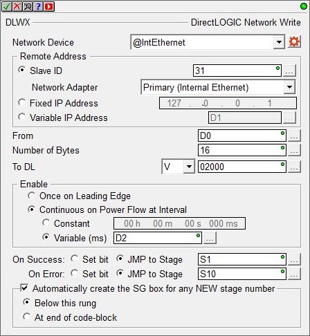
Network Device selects which of the configured Ethernet Devices to use. Click the gear symbol at the right end of the device to open the configuration dialog for the selected device. For more information
on configuring devices go to the Device Configuration section of the System Configuration.
create module indicates that there are no ECOM modules that have been configured to perform this instruction, selecting this option will invoke the Module Configuration selection of the System Configuration where a suitable ECOM module configuration can be created.
Remote Address specifies which of the following addressing modes to use:
-
Slave ID selects the Slave ID (Module ID) of the remote DirectLOGIC slave. This can be any constant value in the range of 1 to 90, or any readable numeric location that contains a value in that range. If Slave ID is selected, then a TCP/IP broadcast is used to perform the network write operation, this means that both the Do-more CPU and the remote ECOM / ECOM100 module must be in the same Broadcast Domain
 A broadcast domain is a logical network segment in which any device connected to the network can directly transmit to any other on the domain without having to go through a routing device. These are typically very basic networks that use hubs rather than switches or routers. A special broadcast address consisting of all 1s is used to send frames to all devices on the network.. Because this selection causes the instruction to use Ethernet broadcasts, you must select which of the Ethernet ports to send the packets through:
Default means the TCP stack will route the packets to the first Ethernet port that can process the packet; on CPUs without a Secondary port (BX-P-ECOMEX) this will always be the on-board port. This is also the proper selection for backwards compatibility with previous Do-more Technology versions and with H2-DM1E, T1H-DM1E, and BX-DM1 CPUs because they have no provision for a Secondary Ethernet port.
Primary (Internal Ethernet) will send packets through the on-board Ethernet port of the Do-more CPU.
Secondary (BRX ECOMEX) will send packets through the BRX CPU's secondary Ethernet port (BX-P-ECOMEX).
-
Select Fixed IP Address to enter the IP Address assigned to the remote slave ECOM module. IP addresses are canonically represented in dot-decimal notation, consisting of four decimal numbers, each ranging from 0 to 255, separated by dots. This can be any valid IP Address on the same local network as the Do-more CPU or the ECOM module.
-
Select Variable IP Address if the IP Address resides in a memory location in the PLC. This allows the IP Address to be changed at runtime. This can be any readable DWord numeric location. Each octet of the IP Address is stored in one byte of the Variable Address location. In the example below the Initialize Data instruction will use the :UB operator to place the 4 octet values of IP Address 192.168.26.71 into the 4 Bytes of the DWord location D0 in the proper order.
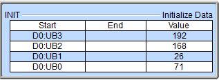
The 'IP Address' format selection in a Data View can be used to see the IP Address stored in the DWord location in the traditional dot-decimal notation (000.000.000.000).
From is the beginning memory address in the Do-more CPU of the data to send to the remote slave. This value can be any readable numeric location.
Note: the DirectNET protocol does not support Bit level writes, it can only write Bytes (8 Bits) of data. This is not an issue when writing Byte, Word or DWord values to V-Memory locations in the remote slave - the thing to remember is that each V-Memory location is 2-Bytes long. To write data from one of the Bit ranges in the Do-more CPU to a remote slave, this field must still be a Byte, Word or DWord location, or evaluate to a numeric location through a Cast operation. For example, to write 1 Byte (8 Bits) from the Do-more CPU starting at C16 to a DirectLOGIC slave enter the value "C16:UB", which is C16 cast to an Unsigned Byte. The Byte of data (8 Bits) at C16 - C23 will be written to the remote slave. And remember, the cast operations must be on Byte boundaries, for example: C0:UB is a valid cast, but C3:UB is not a valid cast.
Note: in most cases, the built-in DirectLOGIC memory blocks DLX / DLY / DLC / DLV should NOT be used as the source location for data sent by the DLX instruction because these memory locations are reserved for use by the Do-more's DirectLOGIC Server (Slave) function. Refer to the DirectLOGIC Memory Blocks diagram in the Memory Configuration section of the System Configuration for more information.
Number of Bytes is designates the number of elements of the selected type to write.
V : each V-Memory location in a DirectLOGIC PLC is 2 bytes in length, so writing V-Memory requires the length be in 2-Byte increments.
X, Y, C, S, T, CT, GX, GY, SP : Bit locations are contained within Bytes of memory, so the length must be in 1-Byte increments.
To DL is the data type and the address to write to in the remote DirectLOGIC CPU. All V-Memory locations in a DirectLOGIC CPU are unsigned 16-bit values. The memory address specifgied value must begin on a Byte boundary, for example X0, X10, X20, X1000, X1770, etc.. Single Bit locations in the DirectLOGIC CPUs cannot be written individually, you must write the Byte that contains the desired Bit. For example, the Byte beginning at X0 contains the BITs X0 through X7, the Byte beginning at X10 contains the Bits X10 through X17. To write to X12, set the 3rd Bit in that Byte to the desired value (0 or 1) then write the entire Byte to X10.
|
V |
0 to 41237 |
|
X |
0 to 1770 |
|
Y |
0 to 1770 |
|
C |
0 to 3770 |
|
S |
0 to 1770 |
|
T |
0 to 370 |
|
CT |
0 to 370 |
|
GX |
0 to 3770 |
|
GY |
0 to 3770 |
|
SP |
0 to 770 |
Enable selects how this instruction will operate. Select from one of the following:
-
Select the Once on Leading Edge option to have this instruction run to completion exactly one time. Typically, this instruction will take more than one PLC scan to complete. Configured this way the instruction is said to be Edge Triggered
Each time the input logic transitions from OFF to ON this instruction will execute. With each execution, this instruction will run to completion even if the input logic transitions to OFF before the instruction completes..
-
Select the Continuous on Power Flow at Interval option to have this instruction run repeatedly as long as the instruction has power flow. After the instruction has initially run, if the instruction still has power flow, the instruction will remain enabled and will wait the specified amount of time before running again. The following options select how much time (in milliseconds) to wait between successive runs. A value of 0ms means the instruction will re-run immediately.
The On Success and On Error parameters specify what action to perform when this instruction completes. You do not have to use the same type of selection for both On Success and On Error.
If the Set Bit selection is used for either On Success or On Error, the specified BIT location will be SET OFF when the instruction is first enabled and will remain OFF until the instruction completes. Once complete, the appropriate Success or Error bit location ON. The specified Bit location is enabled with a SET (Latch) operation meaning that it will remain ON even if the input logic for the instruction goes OFF.
If the JMP to Stage selection is used for either On Success or On Error the target Stage must be in the same Program code-block as this instruction, you cannot specify a target Stage that exists in a different Program code-block. When the operation finishes, the target Stage will be enabled the same way as a standalone Jump to Stage (JMP) instruction would do it. The JMP to Stage option will only be available if this instruction is placed in a Program code-block.
On Success selects which of the following actions to perform if the operation is successful:
- Enable SET Bit then specify any writable bit location.
- Enable JMP to Stage then specify any
Stage number from S0 to S127 in the current Program code-block.
On Error selects which of
the following actions to perform if the operation is unsuccessful:
- Enable SET Bit then specify writable bit location.
- Enable JMP to Stage then specify any Stage number from S0 to S127 in the current Program code-block.
If either the On Success or On Error selections are set to JMP to Stage, Automatically create the SG box for any NEW stage number will be enabled which will automatically create any target stage that does not already exist.
- Below this rung will create the new target stage on a new rung following this instruction.
- At end of code-block will create the new target stage as the last rung of this Program.
Status Display:
The red triangle in the upper left corner of the status display indicates this is a Fully Asynchronous instruction.
See Also:
DLRX - DirectLOGIC Network Read (Do-more PLC <- DirectLOGIC PLC)
DLWX - DirectLOGIC Network Write (Do-more PLC -> DirectLOGIC PLC)
EIPMSG - Send EtherNet/IP Message
PEERLINK - Share Data w / PLCs
RX - Do-more Network Read (Do-more PLC <- Do-more PLC)
WX - Do-more Network Write (Do-more PLC -> Do-more PLC)
Example 1 of 2:
Description of a Typical DirectLOGIC Network Write (DLWX) Stage Diagram:
This is a stage diagram showing a typical sequence that monitors a DL-PLC slave (via an ECOM100) slave and reads up a new recipe whenever it becomes available.
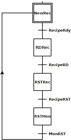
Initially the NewRec (New Recipe) stage monitors a bit from the slave. When this bit comes ON, RecipeRdy (Recipe Ready) causes the transition to the RDRec stage.
The RDRec (Read Recipe) reads the new recipe from the slave. When this completes, RecipeRD (Recipe Read) causes the transition to the RSTRec stage.
The RSTRec (Reset Recipe) writes a bit to the slave to inform it the recipe has been read successfully. When this write is complete, RecipeRST (Recipe Reset) causes a transition to the RSTMon stage.
The RSTMon (Reset Monitor) stage monitors a bit from the slave to confirm the slave heard the reset. When this bit comes ON, MonRST (Monitor Reset) causes a transition back to the NewRec stage to repeat the process and wait for the next new recipe.
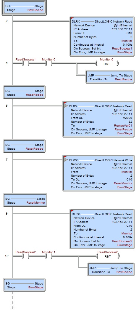
Description of a Typical DirectLOGIC Network Write (DLWX) Stage Ladder:
his is a ladder program that is equivalent to the above stage diagram. It utilizes both the DirectLOGIC Network Read (DLRX) and DirectLOGIC Network Write (DLWX) instructions to monitor a DL-PLC slave (via the built-in Do-more Ethernet port to the DL-PLC's ECOM100) and read up a new recipe whenever it becomes available.
A summary of the master/slave interaction is as follows:
-
The Do-more monitors C10 bit from DL-PLC.
-
The DL-PLC formulates a new recipe and stores it in V2000-2017 memory range.
-
The DL-PLC sets C10 ON when the recipe is ready and begins to monitor for C10 to go back OFF in order to know when the Do-more has read the new recipe up.
-
The Do-more sees C10 turn ON and reads up the new recipe from V2000-2017 memory range and stores it in his memory range RecipeVar01-RecipeVar16.
-
The Do-more then turns the DL-PLC's C10 bit OFF to inform the DL-PLC he has read up the new recipe. Then the Do-more begins to monitor for C11 bit to come ON in order to know the DL-PLC heard him.
-
The DL-PLC sees his C10 bit turn OFF and then turns ON his C11 bit to inform the Do-more he is now formulating the next recipe.
-
The Do-more sees C11 come ON and can now repeat the cycle (return to step 1 above).
 T
T
NewRecipe is the initial stage. The DLRX instruction is set to execute "Continuous at Interval 0.100s" to read a bank of C-bits (C10-27) from the DL-PLC. This word contains the bit the DL-PLC will turn ON when a new recipe has been stored and is ready for the Do-more PLC to read it up. C10 will be stored in Monitor's first bit (Monitor:0), C11 in Monitor's second bit (Monitor:1), etc, until 16 bit are stored. The DLRX reads this bank of bits and stores it in the Monitor word. Upon the successful completion of each read the ReadSuccess1 bit will come ON. When there has been a successful read and the Monitor:0 bit is ON, Rung 3 resets the Monitor:0 bit back OFF (in preparation for the next cycle) and transitions to the ReadRecipe stage. If any one of these reads fails, the DLRX instruction will transition to the ErrorStage where the error can be handled.
The ReadRecipe stage executes the DLRX instruction once to read up the new recipe from DL-PLC's V2000-2017 memory range and stores them in Do-more memory range RecipeVar01-RecipeVar16. Upon a successful read, the DLRX transitions to the ResetRecipe stage. If the read failed, the DLRX instruction will transition to the ErrorStage.
The ResetRecipe stage executes the DLWX instruction once to write the Monitor word (16 bits) down to the bank of C-bits (C10-27) to inform the DL-PLC the new recipe has been read up successfully (i.e. C10 will be written OFF). Upon a successful read, the DLWX transitions to the ResetMonitor stage. If the write failed, the DLWX instruction will transition to the ErrorStage.
The ResetMonitor stage monitors a feedback bit (C11) from the DL-PLC that the DL-PLC should use to inform the Do-more PLC that it "heard" the recipe read was successful and that the DL-PLC can now make preparations for the next recipe. The DLRX reads this bit (C11) by reading the same bank of bits (C10-27) and storing them in Monitor word. Upon the successful completion of each read the ReadSuccess2 bit will come ON. When there has been a successful read and the Monitor:1 bit (i.e. C11) is ON, Rung 10 resets the ReadSuccess2 bit back OFF (in preparation for the next cycle) and transitions back to the initial NextRecipe stage. If any one of these reads fails, the DLRX instruction will transition to the ErrorStage.
The ErrorStage should have code in it (not shown here) that evaluates the various errors that can occur in this example.
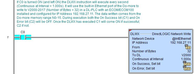
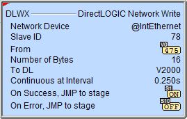
Example 2 of 2: