Topic: DMD0294

Using the Launchpad
Do-more Designer's Launchpad manages
Do-more Projects, provides links to helper Applications, and manages the
communication Links between Do-more Designer and Do-more CPUs.
The Launchpad is both
Dockable![]() A Dockable window is one that can be connected to the sides, top, or bottom of another window.
Docking is done by clicking the mouse in the colored portion of the top bar of the window and dragging it toward the edge of the contain window. As it approaches the containing window, a reverse video block will appear, showing how the docked window will appear in its docked form.and
Floatable
A Dockable window is one that can be connected to the sides, top, or bottom of another window.
Docking is done by clicking the mouse in the colored portion of the top bar of the window and dragging it toward the edge of the contain window. As it approaches the containing window, a reverse video block will appear, showing how the docked window will appear in its docked form.and
Floatable![]() This window can "float" on the screen and remain functional while being unconnected to an edge of a containing window.
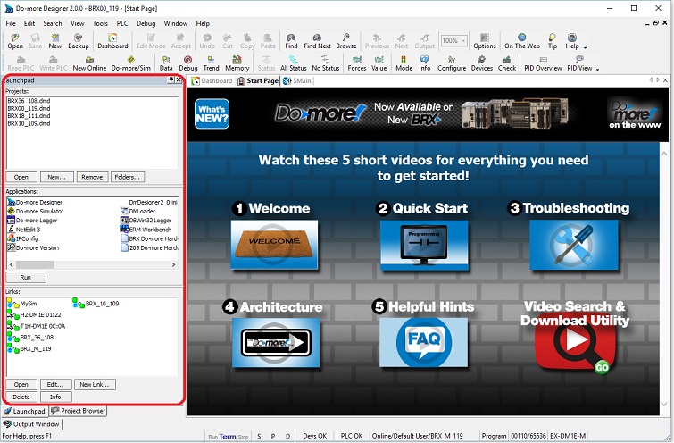
Floating a window is done by clicking the mouse in the colored portion of the top of the window and dragging it away from the edge, As the window is dragged away, a reverse video block will appear, showing how the window will appear in it's floating form..The default location for the Launchpad has a vertical orientation and is docked along the left edge of
the main window as shown below.
This window can "float" on the screen and remain functional while being unconnected to an edge of a containing window.
Floating a window is done by clicking the mouse in the colored portion of the top of the window and dragging it away from the edge, As the window is dragged away, a reverse video block will appear, showing how the window will appear in it's floating form..The default location for the Launchpad has a vertical orientation and is docked along the left edge of
the main window as shown below.
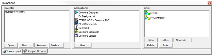
The Launchpad also has a horizontal orientation (as show below). As the Launchpad is docked, it's orientation will change automatically from vertical to horizontal based on the edge where it is docked (vertical for left / right edge, horizontal for top / bottom edge). If the launchpad is undocked it will change the orientation based on it's height versus it's width.
The Global tab of the View -> Options dialog has options to define the layout of the programming environment and some actions for
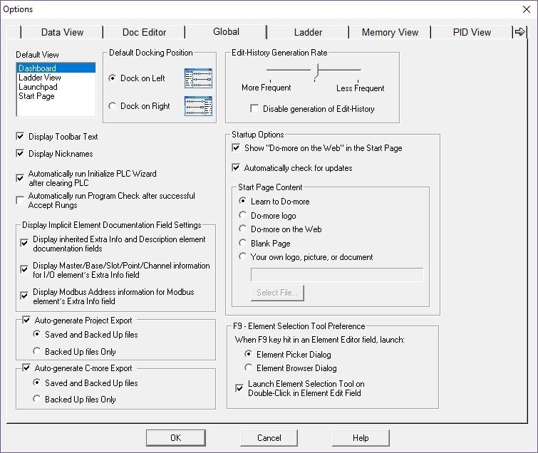
Default View selects what is displayed in the right pane when a new project is opened.
-
Dashboard : the Dashboard will be displayed along with the Project Browser.
-
Ladder View : the Start Page will be displayed, and $Main will be displayed in a Ladder View.
-
Launchpad : the Launchpad will be displayed along with the Project Browser.
-
Start Page : only the Start Page will be displayed.
Default Docking Position selects which edge of the main programming window the Launchpad will dock itself to:
- Dock on Left : dock the Launchpad on the Left side.
- Dock on Right : dock the Launchpad on the Right side.
Display Toolbar Text enables and disables whether the text for each toolbar button is displayed or not. Refer to the Customizing the Toolbars help topic for more options.
Display Nicknames enables and disables the default display of Nicknames for elements that have them. Refer to the Element Documentation help topic for more options.
Automatically run Initialize PLC Wizard after Clearing PLC will optionally run the Initialize Cleared PLC wizard after successfully running a Clear PLC Memory operation.
Automatically run Program Check after successful Accept Rungs will optionally run a Program Check after successfully executing an Accept Rung (F8) operation. Refer to the Program Check help topic for more information.
Display Implicit Element Documentation Field Settings selects which information for the Extra Info and Description will automatically be generated and displayed in the various Views within Do-more Designer. This information does not get saved as part of the element's documentation, this information is only displayed when the element is viewed in Do-more Designer. Text for these fields is only generated if the fields are empty; if these fields have already been edited to include user-specified text, the user's text will be displayed.
Display Inherited Extra Info and Description Element Documentation Fields : if the base element of a structure has been given Extra Info or Description text, the fields of the structure will inherit the same Extra Info and Description text when they are displayed in Do-more Designer. For example, if Timer T0 has been given Extra Info and / or Description text, that same text will be displayed any time any of fields of the associated structure are displayed. Refer to the following:
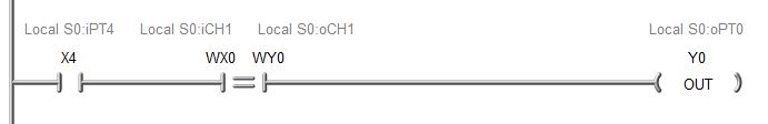
Display Master / Base / Slot / Point / Channel Information for I/O Element's Extra Info Field : when I/O elements in the PLC ( X, Y, WX, WY, RX, RY ) are displayed, their Extra Info field will show their physical location in the PLC system in the form of:
I/O Master that reads and writes their data (Local or number of I/O Master)
Base number
Slot number
Point number (if a discrete I/O point, 0-based)
Channel Number (if an analog I/O channel, 1-based)
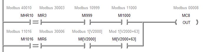
Display Modbus Address Information for Modbus Element's Extra Info Field : when any of the built-in Modbus-specifiec memory locations ( MI, MC, MIR, MHR ) are displayed their Extra Info field will show the fully-qualified Modbus address as shown below:
Auto-generate Project Export each time the project is saved - including auto-saves - or a Backup is generated, all of the project's files, its system configuration, and its documentation will be exported to a text file named <project_name>_EXPORT_DMD.txt
Saved and Backed Up Files the export file will be placed in BOTH the Backup folder and the Project folder.
Backed Up Files Only the export file will be placed in ONLY the Backup folder.
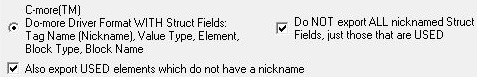
Auto-generate C-More Export : export using the option selections shown below, to a text file named <project_name>_EXPORT_CMORE.txt.
Saved and Backed Up Files each time the project is saved - including auto-saves - or a Backup is generated, the export file will be placed in BOTH the Backup folder and the Project folder.
Backed Up Files Only the export file will be placed in ONLY the Backup folder.
Edit History Generation Rate specifies the frequency that edit history points are generated. Refer to the Edit History help topic for more information on setting the generation rate.
If Disable Generation of Edit History is checked, generating edit history points for any project will stop.
Startup Options define the actions taken by Do-more Designer when it is initially opened.
Show "Do-more on the Web" in the Start Page : enables and disables whether the content from the web site "Do-more on the Web" will be displayed in the top section of the Start Page. Disable the option if the computer running Do-more Designer does not have an Internet connection.
Automatically check for updates : enables and disables the Check for Updates that occurs automatically each time Do-more Designer is started. Refer to the Check for Updates help topic for detailed information on this process.
Start Page Contents specifies what is displayed in the lower section
- Learn to Do-more : (the default) contains links to help topics that are made specifically to help the New -to- Do-more programmers get up to speed quickly with the hardware and software. These topics provide information about where the commonly needed resources are located in the CPUs and what tools are available to the programmer. Everyone new to Do-more Designer and Do-more CPUs will benefit from spending a few minutes reading through the information contained here.
- Do-more logo will display a picture of the Do>more! Logo
- Do-more On the Web will display content retrieved from the 'Do-more on the Web' home page
- Blank Page will display an empty gray background with no image
- Your own logo, picture, or document : this can be any file type that can be displayed in a web browser, such as a text file (.TXT), a web file (.html), a PDF document (.PDF), a Microsoft Word document (.doc / .docx), a picture (.jpg, .bmp, .gif, .tif, .png), etc.. The size of the user document is limited to a maximum of 10 megabytes.
Click the Select File... button which will open the standard file open dialog to browse to the file that will be used as the User document. A confirmation dialog will be displayed, and once confirmed, the selected document will be displayed on the Start Page.
Click here for details on Attaching Individual User Documents to Do-more Designer projects.
F9 - Element Selection Tool Preference selects which of the Element selection tools to use when you press the F9 key on a field where an Element can be entered or edited:
- Element Picker Dialog - (default) : use the Element Picker.
- Element Browser Dialog : use the Element Browser.
If Launch Element Picker Selection tool on Double-Click in Element Edit Field is enabled, double-clicking the mouse on a field where an Element can be edited will open the default Element Picker.
The Projects Section
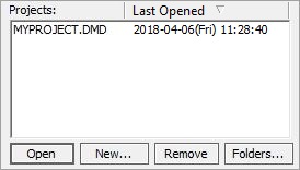
The Projects group will display entries for all of the Do-more Designer projects that have been opened by this copy of the software. Each time a new project is created, or an existing project is opened an entry displaying the project's name will be added to this group.
Open - Open an Existing Project on Disk
If a project in the list has been selected, that project will be opened - Double-clicking on a project name in the list will also execute the 'Open' operation.
If there are no projects listed, or if none of the currently listed projects is highlighted, this dialog will be displayed.
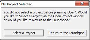
Select a Project will open a File Open dialog so the programmer can browse to the location of an existing Do-more Designer project
Return to the Launchpad will close this dialog and return control to the Launchpad so that an exiting project can be selected.
If the selected project was online with a PLC when it was closed, the project will have the link information stored with it, and so Do-more Designer will attempt to reconnect to that PLC as it opens the project.
If the attempt to reconnect to the PLC using the link specified in the project cannot get online with the PLC the following dialog is displayed:
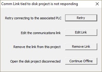
Clicking Retry will try to get online with the PLC again - this could work if the problem was an unplugged cable, PLC turned off, etc.
Clicking Edit Link will open the Link Editor so the parameters of the link can be changed as required.
Clicking Remove Link will remove the link information from the project and open the project in offline mode.
Clicking Continue Offline will leave the link information in the project and will open the project in offline mode.
If the attempt to reconnect to the PLC is successful, Do-more Designer will compare the contents of the offline project with the contents of the project currently in the PLC - this comparison includes the System Configuration, the Programs (code-blocks), the Element Documentation, the Rung Comments, and the Memory Image (if one exists).
If the two copies of the project are the same, the offline project will be displayed.
If the two copies of the project are different in any way, the Resolve Online / Offline Differences dialog will open as shown below:
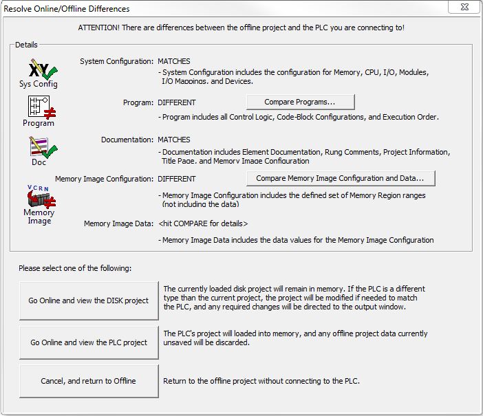
The Details section will list which of the four main components of the project - System Configuration, Program (code-blocks), Documentation, and Memory Image - are different.
If the Program section contains differences, click the Compare Programs... button to open that utility which will generate a detailed listing of those differences.
If the Memory Image Configuration or the Memory Image Data is shown to be different you can click the Compare Memory Image Configuration and Data... button to display a listing of the differences:
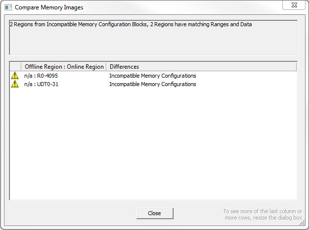
The following lists the possible messages you can see in this dialog and information on how to resolve the issue:
Error Reading Region or Data
A communication error occurred while trying the read the Memory Image data from the PLC.
Incompatible Memory Configurations
The memory configuration for the region in the PLC is different from the memory configuration of a region by the same name in the Memory Image file. No comparison can be done. Use a Write to PLC or Write to Disk operation to synchronize the Memory Configurations between the PLC and the offline project. Then you can use the Memory Image Manager to compare the Memory Image file contents.
Exists Only Offline
The region is not part of the Memory Image file in the PLC. Use a Write to PLC operation to download the Memory Image file to the PLC.
Exists Only Online
The region is not part of the Memory Image file stored on Disk. Use a Write to Disk operation to save the Memory Image file to disk.
Ranges Do Not Match
The region exists in both the PLC copy and the offline copy of the Memory Image file but the range of data in the regions are different. Determine which copy of the Memory Image file has the correct range and use a Write to PLC or Write to Disk operation to get the correct range into both copies of the file.
Ranges Match, but Online Data was Unavailable
The region exists in both the PLC and the Memory Image file, the range of the region matches in both places as well, but the data within the range could not be read from the PLC to do a comparison. This will result if the On Connect option in the Memory Image Manager was set to "Don't Compare On Connect" because the Memory Image data will not be read from the PLC.
Data Does Not Match
The region exists in both the PLC and the Memory Image file, the range of the region matches in both places as well, only the data within that range that is stored in the offline copy does not match the data currently in the PLC. Determine whether the correct data resides in the PLC or in the Memory Image file then use the Memory Image Manager to refresh the contents of the data in the Memory Image file, or download the copy of the data from the Memory Image file to the PLC.
To continue online you must select which copy of the project to display in Do-more Designer:
Go Online and View the DISK Project : selecting this option will display the offline copy of the project.
Depending on the types of differences between the offline and online versions of the project, making this selection can cause a variety of changes that will be made to the version displayed in Do-more Designer that will have to be resolved before the project can be downloaded to the PLC.
One of the more important changes that is possible happens if the CPU type in the Do-more Designer project does not match the CPU type of the online PLC. In this instance the CPU type in the Do-more Designer copy will be changed to match the online PLC's type, and any references in the displayed project to hardware resources of the CPU that no longer exist will be removed and noted in the Output Window. Refer to the Setup Offline PLC help topic for more details on the types of issues that can arise from changing the CPU type of a project.
After making this selection, note that the Write to PLC button on the Online Toolbar is enabled as shown below:
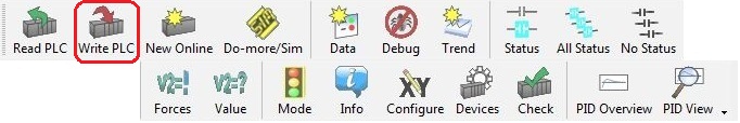
This indicates that there are differences between the project in Do-more Designer and the PLC. Click the Write to PLC button which will open the Project Download dialog to synchronize the projects by downloading the offline copy of the project to the PLC.
Go Online and View the PLC Project : selecting this option will display the copy of the project that was read from the PLC.
Note that the Save button on the Offline Toolbar is enabled as shown below:
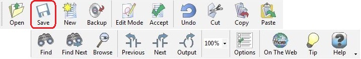
This indicates that there are differences between the copy of the project in Do-more Designer and the copy stored on Disk. Click the Save button to synchronize the projects by copying the Do-more Designer copy of the project to Disk.
Cancel, and Return to Offline : selecting this option will abort the attempt to open a connection to the PLC. Do-more Designer will return to the offline version of the project.
Note: there is a special case in resolving the online / offline differences that involves Edge Bits
Edge Bits hold the scan-to-scan state of the edge-triggered inputs. The value of an Edge Bit is assinged when the project is downloaded to the CPU. Edge Bits are automatically added to the project by Do-more Designer and are for internal use only. and Instruction IDs
When this happens after clicking the Write to PLC button, notice the Save to Disk button on the toolbar will be enabled and the following dialog will open:
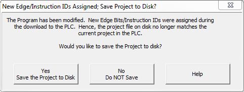
Yes, Save the Project to Disk means the Disk copy will be updated so that the online and offline copies of the project will be match.
No, Do NOT Save means the Disk copy will not be updated with the Edge Bits and Instruction IDs. At this point the online and offline copies of the project will not match. The following message will also appear in the Output Window :
[Message] Modified project not saved to Disk - new Edge / Instruction IDs assigned at download.
The Write to Disk icon will remain enabled and you can should manually save the project to disk at some point so that the new Edge Bits and Instruction IDs in the Disk copy of the project will match the values that are in the PLC.
Help will open the Help Topic to learn more about Edge Bits and instruction IDs.
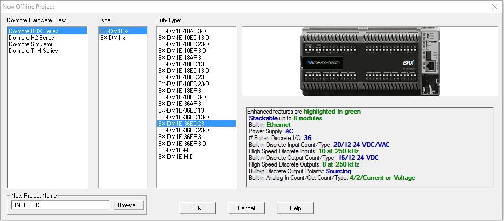
New Offline - Create a New Offline Project
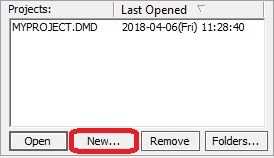
Opens the New Project Dialog which prompts for the following information used to create a new project:
New Project Name
- enter the name for the new project, or browse to an existing project
that will be overwritten. The ".DMD" extension will be automatically added to the project name when the project is saved to
disk. The project name must conform to standard Windows file naming conventions with the exception that the name
cannot contain a period. If an existing project name is selected you will be asked to confirm this operation that will
overwrite all of the information in the existing project.
Do-more Hardware
Class specifies the hardware platform of the CPU and Type
specifies which of the Do-more CPUs built on the specified platform
will be the target device for the new project, Select the appropriate CPU
part number.
Do-more BRX Series - Do-more BRX All-in-One and modular CPUs with BRX series I/O modules.
Type selects which CPU in this series is begin used:
BX-DM1E-x (with on-board Ethernet)
BX-DM1-x
Sub-Type : because the feature set of BRX Series PLCs is largely based on the type of on-board I/O, Do-more Designer needs to know which model number of BRX CPU is being used so that the only the supported features will be made available for use in the project. Select the part number of the CPU.
BX-DM1E-xxYYzz (with on-board Ethernet)
BX-DM1-xxYYzz
Do-more H2 Series - for use with DirectLOGIC 205 hardware.
Type selects which CPU in this series is begin used:
Sub-Type : there are <no PLC sub types> for this series.
Do-more Simulator - for use on a PC running the Do-more Simulator.
Type selects which CPU in this series is begin used:
Sub-Type : there are <no PLC sub types> for this series.
Do-more T1H Series - for use with Terminator I/O hardware.
Type selects which CPU in this series is begin used:
T1H-DM1
T1H-DM1E (with on-board Ethernet)
Sub-Type : there are <no PLC sub types> for this series.
Click the OK button to create the new offline project, and open
that project in the programming software.
Click the Cancel button to exit the dialog and NOT create a new
offline project.
Click the Help button to invoke the Help topic.
Remove - Delete an Existing Project
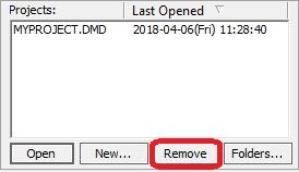
Removes the currently selected project or projects from the Projects list and optionally deletes the project files from disk. Use Ctrl-Click with the mouse to select multiple projects.
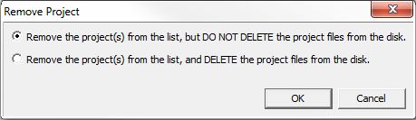
A dialog is displayed with the following two options:
- Remove the project(s) from the list, but DO NOT DELETE the project files from the disk - select this option to remove the project from the Projects list but the files associated with the project will NOT be deleted.
- Remove the project(s) from the list, and DELETE the project files from the disk - select this option to remove the project from the Projects and delete the files associated with the project.
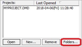
Folders... - Change Project Folder Locations
Opens the Folder Settings dialog that displays the current locations for storing Do-more Designer project files. After opening a project this dialog can be invoked by selecting the File-> Manage Project-> Folders Settings menu item.
The default location is the Projects sub-folder where Do-more Designer is installed. A folder is created in the Projects folder for each project that is saved to Disk.
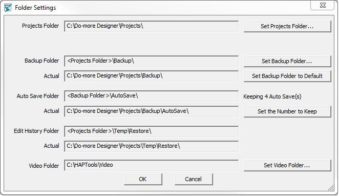
Click the Set Projects Folder button to invoke a dialog that allows the user to select an existing folder, or to create a new folder. It is recommended that the Project Folder be located on the same computer where Do-more Designer is installed. Regardless of the location, the programmer must have write-access to the selected folder.
The project folder for each project will also contain three sub-folders that are used as follows:
Projects Folder - this is the folder that will contain all of the files for each Do-more Designer project.
Click the Set Projects Folder... button to open a dialog that allows the user to select an existing folder, or to create a new folder to begin storing the Do-more Designer projects.
This folder can exist on the hard drive where Do-more Designer is installed, or removable disk, or on a network-accessible disk location. Regardless of the location, the programmer must have write-access to the selected folder.
Backup Folder - designates a location to store backup copies of the projects that are created through the File -> Backup Project operation. The default location is the \Backup folder where the Do-more Designer Projects are stored.
Click the Set Backup Folder button to open a dialog that allows the user to select an existing folder, or to create a new folder to begin storing the backup copies of the projects.
This folder can exist on the hard drive where Do-more Designer is installed, or removable disk, or on a network-accessible disk location. Regardless of the location, the programmer must have write-access to the selected folder.
Click the Set Backup Folder to Default button to reset the backup folder to it's default location of <Projects Folder>\Backup.
Auto-Save Folder specifies a location to store copies of the projects created by the Auto-Save process. A complete discussion on the Auto Save process is available in the section on Project Backup and Restore.
Keeping 4 Auto Save(s) displays the number of Auto Saves that Do-more Designer will keep on disk.
Click the Set Number to Keep button to display a dialog with the following options:
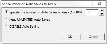
- Specify the number of Auto Saves to Keep (1 - 100) : enter the number to keep.
- Keep UNLIMITED Auto Saves : Auto Saves will not be deleted by Do-more Designer.
- DISABLE Auto Saving : the Auto Save process is disabled, no Auto Saves will be created. A complete discussion on the Auto Save process is available in the section on Project Backup and Restore.
Edit History Folder specifies a location to store copies of the project created by the Edit History process.
Video Folder specifies the folder where the training videos were stored when Do-more Designer was installed, and where any videos downloaded by the Video Download Utility will be stored.
Click the Set Video Folder... button to open a dialog that allows the user to select an existing folder, or to create a new folder where additional downloaded videos will be stored.
The Applications Section
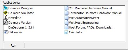
The Applications group contains links to applications and utilities that are used in conjunction with Do-more Designer. There are also links to web sites that contain additional useful information that make using the programing software easier.
Run executes the item that is highlighted. Double-clicking on an application name in the list will also execute the 'Run' operation.
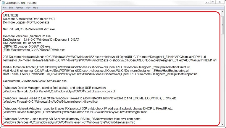
The entries that are listed in the Applications section are contained in the file DmDesigner1_3.Ini (the 1_3 represents v1.3 of the software, these two digits will be the software version currently running). You can edit this file and change the entries in the list by clicking the DmDesigner1_3.ini selection in the list. This will open DmDesigner1_3.ini in the default text editor (typically Notepad). The individual entries are listed in the UTILITIES group.
You can keep any of the application in this group from being displayed by commenting it out the selection in the Ini file. This is done by placing a semicolon as the first character on each line that contains the utility description. For example, in the image below, DBWin32 Logger, ERM Workbench, Windows Network Control Panel, Windows Firewall, Windows Device Manager, and Windows Services have been disabled.
Make whatever changes you need to this Ini the save the file. You must restart Do-more Designer to have the changes take effect.
The Links Section
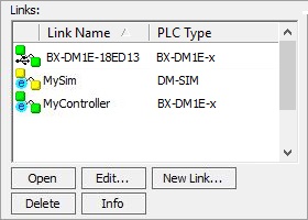
The Links group contains icons representing communication links to Do-more CPUs that have been created by this copy of the software. The Link Name column shows the name assigned to the link, and the PLC Type column will show the PLC family the link was configured to connect to.
There are different link icons for
each communication port type that can be used by Do-more Designer:
Ethernet : links that utilize an Ethernet port will have a lowercase 'e' in the icon
Serial : links that utilize a serial port will have a lowercase 's' in the icon
USB : links that utilize a USB port will have a lowercase 'u' in the icon
Modem : links that utilize a modem will have a lowercase 'm' in the icon
When Do-more Designer starts up, it steps through each of the links
in the list and checks to see if the CPU that is defined in the
link is currently accessible. The link icon uses color to convey the current
connection status of each link icon as follows:
Green means the CPU is currently accessible using the parameters currently defined in that link
Yellow means the CPU is NOT currently accessible using the parameters currently defined in that link, this could be because the communication cable is unplugged, or the CPU is turned OFF, or that the communication parameters in the link no longer match the port setup on the CPU.
Open : highlighting a link and clicking the Open button or double-clicking on a link icon in the list will cause the programming software to attempt to go online with the CPU using the port parameters as defined in the currently highlighted link. If the contents of the CPU match a disk-based project the programmer will be given the option to open that disk based project. Click here for more details on that process.
Edit... will open the Configure Link dialog for the currently highlighted Link so that the communication parameters of that link can be modified. A communication link cannot be modified if it is currently being used by a Do-more Designer session.
New Link... will open the Select PLC Connection utility showing only PLCs that are not currently used in a connection so that a new connection to PLC can be created.
Delete will delete the currently highlighted Link. A link that is currently in use by a programming session cannot be deleted.
Info will open the Link Info dialog for the currently highlighted Link so that the current status of that communication link can be viewed.
See Also:
Related Topics: