Topic: DMD0357

Element Picker
When the edit cursor moves to a parameter that is editable, the Element Picker dialog will automatically open and display all of the programming Elements that are valid for that parameter. The programming Elements will be displayed on the dialog in the Element Picker in the following two forms:
- A tree control with notations similar to the ones found in the Project Browser. This makes it very easy to browse through all of the possible programming elements for each instruction parameter.
- A grid that shows which Elements adjacent to the current Element in the Element Edit field are already used in the project.
In Do-more Designer versions 1.4 and later, the Element Picker is the preferred element selection tool, meaning that it that will be opened anytime the edit cursor moves to an editable parameter in ans instruction, or any time the F9 key is pressed when the cursor is on an element field. For those who would prefer to use the Element Browser see below.
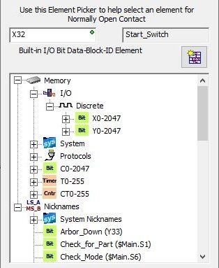
The top portion of the Element Picker contains the tree control that is used to browse through the various programming elements that are available for the field. The topmost fields display the Element, the Nickname for that element (if one exists), and a textual description of the type of the current element.
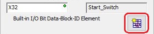
Clicking the Create Data Block button will open the following dialog where the user can create a new block of data for use in the current parameter field:
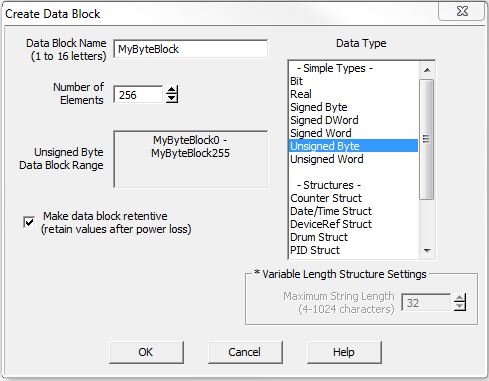
The Data Block Name must be unique, and consist of 1 to 16 characters (A-Z, a-z; no numbers, no spaces).
Data Type selects the type of data the block will consist of:
Each of the Simple Types elements of the data block will be the same type. Select the type from the list.
Each Structures of the data block will be a structure. Select the type of structure from the list.
Variable Length Structure Settings is required if the structure specified is a String Struct, enter the maximum length of the Strings in the data block.
Make Data Block Retentive will have each element in the block hold its state through a power cycle or a Program-to-Run mode transition. The status of memory NOT marked as retentive will be cleared at power up and during a Program-to-Run mode transition.
The center section is the tree control that contains the list of Elements that are appropriate selections for the current field. The list has two main groups: Memory and Nicknames.
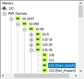
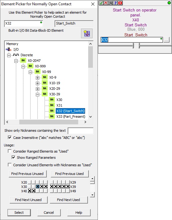
Memory is an expandable list of all the Elements that can be used in this parameter by memory type. An element is selected from the list by expanding the appropriate level and repeatedly until you get to the individual element you want to use in the current parameter. Refer to the image below where Element X32 is selected by expanding the levels starting with I/O -> Discrete -> X0-2047 -> X0-999 -> X0-99 -> X30-39 -> X32.
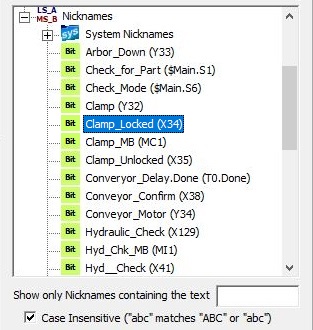
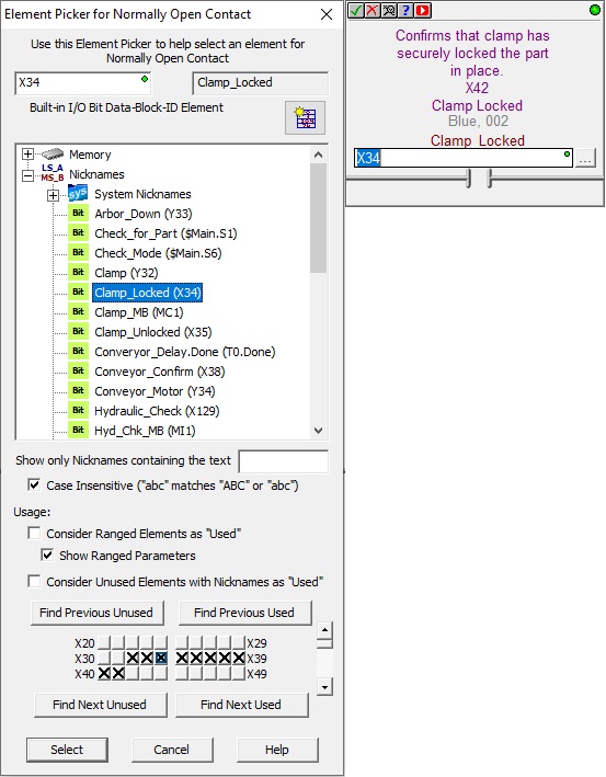
Nicknames is a list of the Elements that have a user-assigned Nickname; the list is sorted alphabetically. This section also includes the System Nicknames which are Elements that have system-assigned Nicknames.
The two selections below the tree control are used to refine the list of Nicknames elements. Show only Nicknames containing the text will list only Nicknames that contain the text entered in the field provided. Case Insensitive will toggle whether or not the text entered must match the case of the Nickname.
An element is selected from this list by expanding the Nickname list and scrolling to find the individual element you want to use in the current parameter. Refer to the image below where Clamp_Locked (X34) is selected.
The bottom portion shows a Usage table, where the range of programming Elements that are adjacent to the one selected are shown. An Element can be selected by clicking on the Element's corresponding square in the grid.
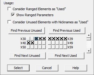
When Consider Ranged Elements as "Used" is enabled, if a range of elements is used as a parameter in an instruction, all of the elements within that range will be treated as "already used" by the four "Find ..." operations.
When Show Ranged Parameters is enabled, if a range of elements is used as a parameter in an instruction, all of the elements within that range will be marked in the Usage grid . For example, if a Reset Range (RSTR) instruction uses D0 through D9 as a parameter, then all of the elements in that range (D0, D1, D2, D3, D4, D5, D6, D7, D8, and D9) will be marked in the Usage grid. When not enabled, only the first and last elements of the range will be marked as used - because these are the two elements (D0 and D9) used in the instruction.
Consider Unused Elements with Nicknames as "Used" means that elements that have a Nickname will be marked as "already used" even if they are not currently used as a parameter in an instruction.
Starting at the current Element, there are four buttons that can help located the following:
Find Previous Unused looks backwards through the current data block to locate the first element in that range that IS NOT already used in the project.
Find Previous Used looks backwards through the current data block to locate the first element in that range that IS being used in the project.
Find Next Unused looks forwards through the current data block to locate the first element in that range that IS NOT already used in the project.
Find Next Used looks forwards through the current data block to locate the first element in that range that IS being used in the project.
The usage grid contains one block per element; the current element will have a border cursor (D17 is the image below).
Instruction Requires a Non-Stage Parameters
When editing a field that does NOT require a Stage bit, the blocks in the usage grid will be displayed as one of the following:
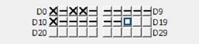
blank means the Element is not used in the project.
X means the Element is used as a parameter in an instruction.
-- means the Element is in a range that is used in an instruction.
Instruction Requires a Stage Bit Parameter
When editing a field that requires a Stage bit (for example Jump to Stage (JMP), or the On Success / On Error parameters of Asynchronous Communication instructions), the blocks in the usage grid can show the following that provide not only usage data but context information as well:
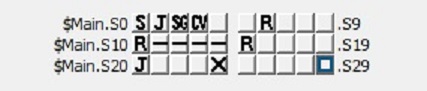
blank means the Element is not used as a Stage parameter.
X means the Element is used in more than one Stage instruction, for example it is used in a Jump to Stage (JMP) instruction and a Stage (SG) instruction.
-- if Show Ranged Parameters is enabled, this means the Element is in a range that is used in a Disable a Range of Stages (SGRST) instruction.
SG - means the Element is used exclusively in a Stage (SG) instruction but has NOT yet been used in a Jump to Stage (JMP) instruction.
J means the Element is used exclusively in a Jump to Stage (JMP) instruction but has NOT yet been used in a Stage (SG) instruction.
S means the Element is used exclusively in an Enable Stage (SGSET) instruction but has NOT been used in any other Stage instruction.
R means the Element is used exclusively in a Disable Stage (SGRST) or a Disable a Range of Stages (SGRST) instruction but has NOT been used in any other Stage instruction.
CV means the Element is used in a Converge Multiple Stages to SG (SGCONVRG) instruction but has NOT been used in any other Stage instruction.
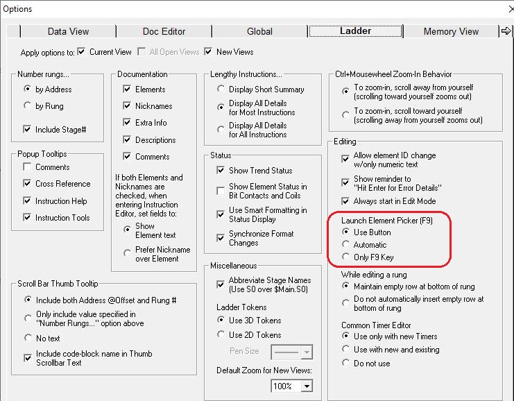
By default, the Element Picker is automatically opened any time an instruction is being edited and the edit cursor is on a field that can be changed by the Element Picker. This automatic behavior can be changed the Ladder tab of the View -> Options dialog to one of the three following options:
Use Button will only open the Element Picker when you click the "..." button to the right of a parameter field.
Automatic will open the Element Picker any time an instruction is being edited and the edit cursor is on a field that can be changed by the Element Picker.
Only F9 Key will only open the Element Picker when you press the F9 key.
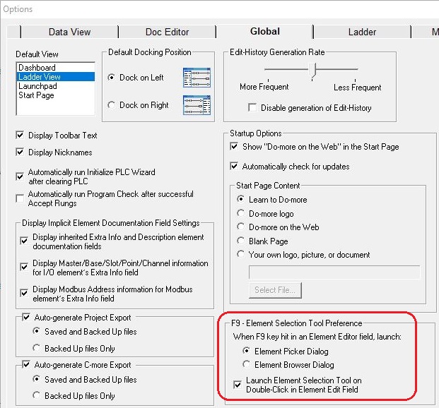
Making the Element Picker the Preferred Element Selection Tool
By default, the Element Picker is the preferred Element Selection Tool across all of Do-more Designer, meaning that is the tool that is launched when the user presses F9 while editing any Element field. You can change this selection to use the Element Browser on the Global tab of the View -> Options dialog.
There is also an option to open the desired Element Selection Tool with a double-click on an element parameter field in an instruction editor.
Below are some examples of using the Element Picker to select the major different types of Elements:
Selecting a Discrete Input by Element
Selecting a Discrete Input by Nickname
Selecting a Structure Field

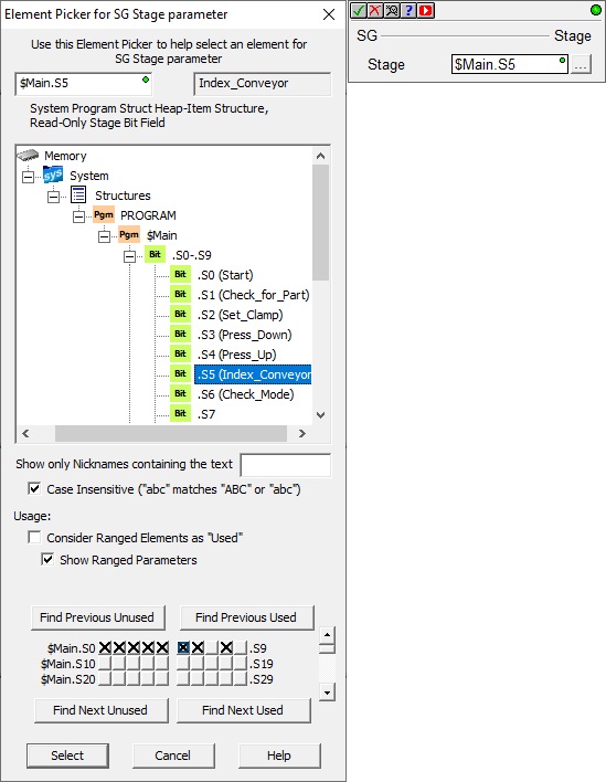
Selecting a Stage
See Also:
Using the Cross Reference View
Related Topics:
Using the Documentation Editor