Topic: DMD0220

The Ladder Editor
The ladder logic diagrams for all of the code-blocks is created and edited using the ladder editor. This editor is optimized to make the editing process as fast and intuitive as possible. It has options for both mouse-centric and keyboard-centric methods for selecting instructions and the programming elements used as parameters.
|
|
Cut, Copy, and Paste Individual Instructions | Insert Rungs, Rows, or Columns |
Edit Mode vs. Display Mode
Ladder Views have two viewing modes; the Display Mode and the Edit Mode. When a project is first opened, the Ladder View will be in the Display Mode, which is only a viewing mode. A code-block cannot be edited in this mode. In order to edit the contents of a code-block, the Ladder View must be in the Edit Mode. To enable the Edit Mode, either click on the Edit Mode button on the Offline toolbar, or select the Edit -> Edit Mode menu option, or use the keyboard shortcut Ctrl+E.
There is visible confirmation that the Edit Mode is enabled: the edit cursor changes from a hollow box to a solid box, the background changes for the Edit Mode button on the Offline toolbar, and the elements in the Instruction Toolbox are enabled.
Edit Mode and Display Mode are not selected for individual code-blocks, meaning that if there are multiple code-blocks open at the same time, enabling Edit Mode for any Ladder View enables Edit Mode for all of the currently open Ladder Views, and any Ladder Views that are opened while Edit Mode is enabled.
Edit Mode only applies to Ladder views; the System Configuration and Element Documentation can be changed without Edit Mode being enabled. The Project Browser DOES require that a code-block be in edit mode before the configuration of that code-block can be changed.
Project Changed Bars
As edits are made to the contents of a code-block, Do-more Designer will display one or more of the three colored bars to the left of the rung's number. These colored bars indicate that the project has been changed and some additional actions are required to complete the changes.
A
A
A
Note: at the same time the Write PLC button was enabled, the Read PLC button was also enabled. This allows the programmer the option to restore the program to the state that it was before the changes were made. The Read PLC operation will refresh the screen with the previously saved version of your program.
Note: the Project Differences indicators on the Status Bar will also indicate any differences between the Disk and PLC versions of the project.
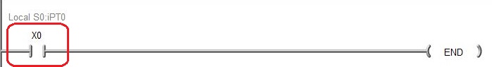
How to Enter Contacts
After enabling Edit Mode, after placing the block cursor on the desired location on the rung, entering new contacts on a rung can be done
using any of the following methods:
Instruction Toolbox - drag and drop the contact from the Instruction Toolbox to the desired location on the destination rung, or double click on the contact in the Instruction Toolbox to place the contact at the location of the block cursor.
Contact Browser (F4) - press the F4 key to invoke the Instruction Browser where the desired type of contact can be selected from a list. Once the contact is selected, the Contact Browser dialog will close and the contact instruction editor will open so that the parameters for the selected contact can be entered.
Function Key or Hot Key - place the edit cursor at the desired location on the rung then press the Function key or Hotkey associated with the desired contact. This will open the contact instruction editor where the parameters for the selected contact can be entered.
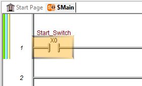
Type the name of the Memory location or its Nickname - this will create a normally-open contact at that location on the rung and open the contact instruction editor where the parameters for the selected contact can be entered. Use the forward-slash key ( / ) to toggle between a normally open and normally closed contact.
Double-click at the desired location - this will create a normally-open contact at that location on the rung and open the contact instruction editor where the parameters for the selected contact can be entered. Use the forward-slash key ( / ) to toggle between a normally open and normally closed contact.
Use the Ladder Instruction Palette - place the edit cursor at the desired location on the rung then left-click the desired contact symbol on the Instruction Palette. This will open the contact instruction editor where the parameters for the selected contact can be entered.
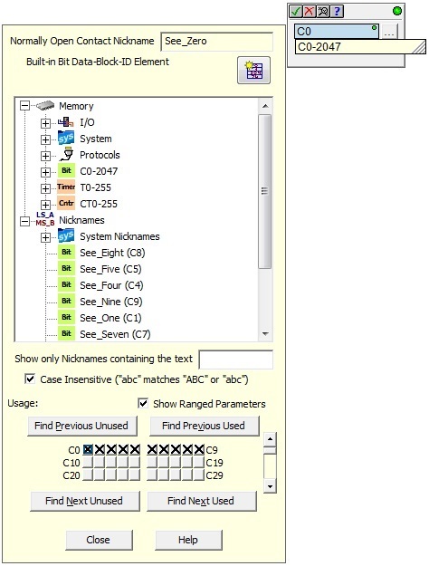
After selecting the type of contact to enter, the Contact Instruction Editor will be displayed with either the parameter that was selected, or with the default parameter for the type of Contact selected. The Element Picker will also open to assist in navigating through all of the potential elements that can be used as a parameter in the current field of this instruction:
The Ladder View -> Options setting for the Element Picker controls how it operates in the Ladder Editor:
Launch Element Picker (F9) options select what action will open the Element Picker dialog when editing an instruction:
- Use Button (default) means the Element Picker dialog will not open automatically; you will need to click on the "three button" graphic to the right of the parameter field to open the Element Picker.
- Automatic means the Element Picker dialog will open automatically; the "three button" graphic to the right of the parameter field is NOT displayed.
- Only F9 Key means the Element Picker dialog will not open automatically; the "three button" graphic to the right of the parameter field is NOT displayed; you will need to press the F9 key top open the Element Picker.
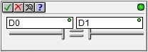
Take note of the circle in the upper right corner of the editor, and a similar one in the parameter field.
A
If the
green circle changes to
A
If you would rather not use the Element Picker to select the element for this field of the instruction, you can continue to enter characters until the complete element address is entered. And while the parameter field is being edited, the instruction will display an "auto-complete" drop-down below the parameter field. This drop-down will display any valid range of memory locations that match the characters as they are entered in the field. As more characters are entered the ranges displayed will change to continue displaying matches.
If there are no characters in the parameter field, pressing the down arrow will display the drop-down list of all the Ranges of Memory Elements and individual memory elements that are valid for this contact type. Use the down arrow or the thumb bar to scroll through the list. As the cursor moves through the list the Item or Range under the cursor is entered in the parameter field. If the value is one of the Ranges of Memory Elements, the parameter will need to be edited further so that just the one parameter from that range remains in the field.
![]()
There is one notable exception to this functionality, that is when the cursor is over a structure field. The initial auto-complete drop-down list will only display the name of the structure, not the individual fields that the structure contains. When the structure name is selected and the programmer enters a "." after the name, the drop-down list will display all of the fields of that structure which are valid for use in a Contact. This new list can then be navigated in the same manner described above and the desired structure field can be selected by pressing the Enter key.
![]()
Relation Contacts
Relational Contacts have two parameters that must be entered. The process of entering the parameters for the fields is the same as is used for normal contacts. Pressing the Tab key will move the edit cursor from one parameter field to the other. Because the relational contacts contain arithmetic operations, the down-arrow auto complete list will additionally contain valid ranges of constant values.
Adding Nicknames Instead of PLC Elements
An alternative to assigning a PLC element to the contact at this point is to enter user-defined text (sometimes called a Tag name) that will be used an alternative name for the element (Do-more Designer calls this a Nickname).
Any time an instruction editor is closed with an unknown Element reference, Do-more Designer will assume this text is to used as a Nickname and will open the Create Nicknames dialog. Once a Nickname has been assigned to an element, the Nickname and the Element ID can be used interchangeably within the project. At this point you can assign the nickname an Element ID, or just specify the type of element it will eventually refer to (this will create an Unassigned Nickname that must be resolved before the project can be downloaded to a PLC).
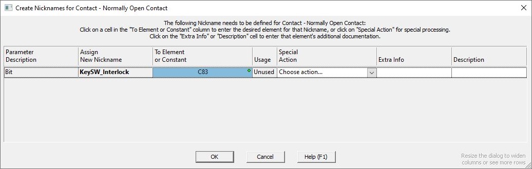
Parameter Description, Assign New Nickname, and To Element or Constant fields are derived from the instruction's parameter fields. Usage indicates whether the Element is already used in the ladder logic program.
Special Action column contains options to change the Nickname processing:
- Find Next Unused (Ctrl+N) will find the next unused element of the same type as the entered parameter.
- Browse ... (F9) will open the Element Picker where a new memory element can be selected for the parameter.
- Make Unassigned will create an "unassigned nickname" of the appropriate type (Bit or Numeric or Structure) that can be resolved at a later time with the Assign Nickname utility. Note: be aware that while a project that contains any unassigned Nicknames can
be saved to disk, that project cannot be written to the PLC.
This is because the PLC can only use PLC element references as instruction parameters,
it can not use the only Nicknames as parameters.
- Do not Create This Nickname will return to the instruction editor without creating the Nickname for the specified Element.
Extra Info and Description fields allow for adding additional text for the Nicknames while they are being created.
After supplying the required parameters for all of the fields in the instruction, pressing the Enter key or clicking on the button with the check mark in upper left corner of the Contact Instruction editor will enter the contact on the rung and the edit cursor will move to the next entry position. A vertical yellow change bar will appear to the left of the left of the rung. The yellow bar indicates that some type change has been made to the rung but the change has not been Accepted.
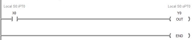
How To Enter Output Coils
Entering output coils on a rung is a very similar process to entering
contacts, the main difference is that all of the output coils are placed
in a single column at the far right edge of the Ladder View, this is called
the output column. After enabling Edit Mode, entering new coils on a rung can be done using
any of the following methods:
Instruction Toolbox - drag and drop the Instruction Toolbox to the desired location on the destination rung, or double click on the coil in the Instruction Toolbox to place the coil at the location of the block cursor.
Coil Browser (F5) - press the F5 key to invoke the Instruction Browser where the desired type of coil can be selected from a list. Once the coil type is selected, the Instruction Browser dialog will close and the coil instruction editor will open so that the parameters for the selected coil type can be entered.
Double-click in the output column on the desired rung - this will create an output coil on the rung and open the coil instruction editor where the parameters for the coil can be entered.
Type the name of the Memory location or its Nickname - this will create an Output Coil at that location on the rung and open the coil instruction editor where the parameters for the selected contact can be entered.
Place the edit cursor in the output column and type the name of the Memory location or its Nickname - this will create an output coil on the rung and open the coil instruction editor where the parameters for the coil can be entered.
Use the Ladder Palette - place the edit cursor in the output column on the rung then left-click the desired coil symbol on the palette. This will open the coil instruction editor where the parameters for the selected coil can be entered.
After selecting the type of coil to enter, the Coil Instruction editor will be displayed with either the parameter that was entered, or with the next unused default parameter for the type of Coil selected. And the Element Picker will also be opened to assist in navigating through all of the potential elements that can be used as a parameter in the current field of this instruction. The Coil Instruction editor provides the same auto-complete functionality that is described above with Contacts.
After supplying the required parameters, pressing the Enter key or clicking on the button with the check mark in upper left corner of the Coil Instruction editor will enter the coil on the rung. A vertical yellow change bar will appear to the left of the rung. As noted earlier, the yellow bar indicates that a change has been made to the rung but the change has not been Accepted.
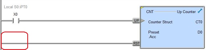
How to Enter Box Instructions
Like output Coils, all Box instructions are placed in a single column
at the far right edge of the Ladder View, this is called the output column. After enabling Edit Mode, entering new boxes on a rung can be done using
any of the following methods:
Instruction Toolbox - drag and drop the box instruction from the Instruction Toolbox to the desired location on the destination rung, or double click on the box instruction in the Instruction Toolbox to place the instruction at the location of the block cursor.
Box Browser (F7) - press the F7 key to invoke the Instruction Browser where the desired box instruction can be selected from a list. Once the box is selected, the Instruction Browser dialog will close and the box instruction editor will open so that the parameters for the selected box can be entered.
Place the edit cursor in the output column and type the mnemonic of the Box Instruction - this will create that instruction on the rung and open the box instruction editor where the parameters for the box can be entered.
Use the Ladder Palette - place the edit cursor in the output column on the rung then left-click the desired box instruction mnemonic on the palette. This will open the box's instruction editor where the parameters for the selected instruction can be entered.
Because the Box instructions vary greatly in number of parameters and complexity, each Box instruction has it's own editor. Each of the Box Instruction editors provides the auto-complete functionality where appropriate, and it will operate similarly to what is described above with Contacts and Coils.
After supplying the required parameters, pressing the Enter key or clicking on the button with the check mark in upper left corner of the Box Instruction editor will enter the box on the rung. A vertical yellow change bar will appear to the left of the rung. As noted earlier, the yellow bar indicates that a change has been made to the rung but the change has not been Accepted.
Power rail instructions are box instructions that are displayed in the power rail of the Ladder View, not in the output column like the other box instructions. The following is a list of the power rail instructions:
SGCONVRG
- Converge Multiple Stages to SG
REPEAT - Loop Until Condition is Non-Zero
UNTIL
- Repeat Until Condition is Non-Zero
WHILE - Loop While Powerflow is True
Entering any of these power rail instructions requires special consideration because, even though these instructions ultimately end up in the left-most column of the ladder diagram (the power rail), they are still created in the right-most column of the ladder logic diagram (the output column). This makes creating the instructions in Do-more Designer a bit counter-intuitive in that the first step is to position the edit cursor in the output column of the ladder logic diagram (the far right) instead of positioning it against the power rail (the far left).
After selecting the type of power rail instruction the Box Instruction editor will then be displayed in the far left column (the power rail).
After entering the required parameters for the power rail instruction the box will be drawn as follows:
Cut, Copy, and Paste Individual Instructions
Individual Contacts, Coils and Box Instructions on a rung can be Cut, Copied and Pasted. You cannot select multiple contacts, coils, or box instructions for these operations, only individual program elements can be manipulated. You can optionally select an entire rung for Cut, Copy and Paste as described below.
Begin by positioning the block cursor over the element to Cut or Copy.
To Cut the element press Ctrl + X or right click -> Cut which will remove the element from the rung and place a copy of that element in the clipboard.
To Copy the element press Ctrl + C or right click -> Copy which will leave the element in place on the rung and place a copy of the element in the clipboard.
To Paste a copy of the element on the same rung - or a different rung - move the block cursor to the position on the destination rung where you want to place the copy and press Ctrl + V or right click -> Paste. Depending on what type of programming element is being pasted and what is on the rung where the block cursor is located will determine what happens next.
Note: if the paste operation did not place the Contact, Coil or Box Instruction in the desired location, use the Ctrl + Z (Undo) to revert back to a version of the rung before the paste operation was performed.
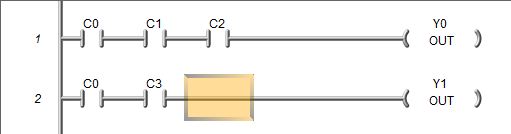
Paste Operation with Contact
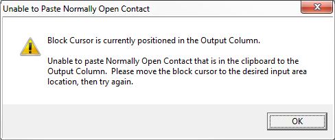
If the paste operation will be performed at an empty location on the destination rung, a copy of the contact in the clipboard will be placed there will no addition input from the user. If a contact already exists at the location on the destination rung the following dialog will open prompting the user for the required additional information:
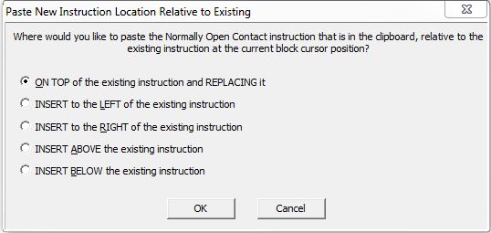
ON TOP of the existing instruction and REPLACING it - this will remove the contact at the block cursor position and replace it with the contact in the clipboard..
INSERT to the LEFT of the existing instruction - this will insert a new column to the left of the existing instruction and place a copy of the instruction in the clipboard in the new column.
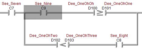
Note: if there is a vertical wire immediately to the left of the block cursor, the paste operation will place the new instruction to the left of the wire, NOT to the left of the contact. In the screen shot below, the contact C9 was copied. Notice the block cursor includes the wire immediately to the left of the contact.
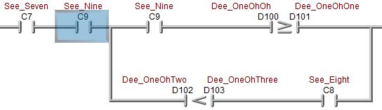
Here is the result after pasting "TO THE LEFT OF" C9:
INSERT to the RIGHT of the existing instruction - this will insert a new column to the right of the existing instruction and place a copy of the instruction in the clipboard in the new column.
INSERT ABOVE the existing instruction - will insert a new row above the row with the block cursor and place a copy of the contact in the clipboard in the new row at the column position of the block cursor.
INSERT BELOW the existing instruction - will insert a new row below the row with the block cursor and place a copy of the contact in the clipboard in the new row at the column position of the block cursor.
If the block cursor is located in the output column when the paste operation is executed you will get an error message similar to the following:
Paste Operation with a Coil or Box Instruction
If the paste operation will be performed on a rung that has a NOP in the output column, a copy of the Coil or Box instruction in the clipboard will be placed there will no addition input from the user. If a Coil or Box instruction already exists in the output column of that rung the following dialog will open prompting the user for the required additional information:
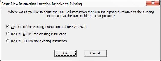
ON TOP of the existing instruction and REPLACING it - this will remove the Coil or Box instruction at the block cursor position and replace it with the Coil or Box instruction in the clipboard.
INSERT ABOVE the existing instruction - will insert a new row above the row with the block cursor and place a copy of the Coil or Box instruction in the clipboard in the output column of the new row.
INSERT BELOW the existing instruction - will insert a new row below the row with the block cursor and place a copy of the Coil or Box instruction in the clipboard in the output column of the new row.
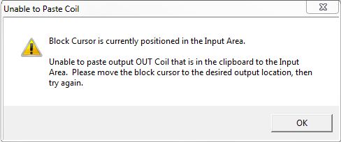
If the block cursor is not located in the output column when the paste operation is executed you will get an error message similar to the following:
How To Delete Contacts, Coils, and Box Instructions
Deleting contacts, coils or box instructions from a rung of ladder logic is accomplished by enabling Edit Mode, then placing the Edit cursor over the contact, coil or box instruction to be deleted and pressing the Delete key, or the Edit -> Delete menu selection. Deleting an Element from a rung will leave a gap in the connecting wire that must be filled before the rung can be saved to the project.
The Backspace key can also be used to delete the contact to the immediate left of the edit cursor. Unlike the Delete operation which will leave a gap in the connecting wire, this operation will redraw the connecting wire in place of the deleted contact.
Depending on what element was deleted, and where it was located on the ladder logic rung, the delete process may leave a gap in the connecting wire. A gap in the connecting wires can be corrected by drawing a connecting wire or possibly just Accepting the changes (which will optimize the rung and redraw it if needed).
How To Draw Wires Between Contacts and Coils
Creating complex ladder logic requires the ability to "draw" networks of input contacts and the ability to connect multiple output coils or box instructions in parallel. Do-more Designer uses the Ctrl key with the arrow keys to draw connecting wires in the direction of the arrow.
Wire Right (Ctrl + Right Arrow) - draws a horizontal wire in the current cursor location and moves the cursor to the right. Drawing a connecting wire over the top of a contact will not delete that contact; it will simply connect it if needed.
Wire Left (Ctrl + Left Arrow) - draws a horizontal wire in the current cursor location and moves the cursor to the left. Drawing a connecting wire over the top of a contact will not delete that contact; it will simply connect it if needed.
Wire Down (Ctrl + Down Arrow) - draws a vertical wire along the left edge of the edit cursor down from the current cursor location and moves the cursor down to the next row.
Wire Up (Ctrl + Up Arrow) - draws a vertical wire along the left edge of the edit cursor up from the current cursor location and moves the cursor up to the previous row.
Wire to Output Column (Ctrl +W) - draws a connecting wire from the current cursor location all the way to the output column. Pressing it again will remove the connecting wire that was just drawn.
During the process of editing ladder logic rungs, there will be times when a connecting wire needs to be deleted. Do-more Designer uses the Ctrl key and the Shift key with the arrow keys to delete connecting wires in the direction of the arrow.
Wire Delete Right (Ctrl + Shift + Right Arrow) - deletes the horizontal wire or programming element in the current cursor location and moves the cursor to the right.
Wire Delete Left (Ctrl + Shift + Left Arrow) - deletes the horizontal wire or programming element in the current cursor location and moves the cursor to the left.
Wire Delete Down (Ctrl + Shift + Down Arrow) - deletes the vertical wire along the lower left edge of the edit cursor and moves the cursor down to the next row.
Wire Delete Up (Ctrl + Shift + Up Arrow) - deletes the vertical wire along the upper left edge of the edit cursor and moves the cursor up to the previous row.
How To Insert Rungs, Rows, or Columns
There will be times when building ladder logic programs that space for additional rungs or more space on existing rungs is needed. The Insert dialog allows the programmer to insert additional rungs to a ladder logic program, or add additional rows or columns to existing rungs. These operations are handled through the Insert dialog.
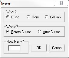
What? - designates whether Rungs, Rows or Columns are to be inserted
Rung - insert one or more empty rungs before or after the current rung. The Rung Comment location will be preserved.
Row - insert one or more empty rows into the current rung. Rows can be inserted before or after the current row. Insert rows to create parallel branches of ladder logic, or additional outputs. Vertical wires are stretched through newly inserted row to preserve parallel connections. Box instructions with multiple inputs are extended when rows are inserted to preserve input connections.
Column - insert one or more empty columns into the current rung. Columns can be inserted before or after the current column. Use insert column to create space for a new contact before an existing contact. Horizontal wires are extended through newly inserted columns to preserve connections.
Note: to quickly insert one new row before the current row, place the edit cursor at the far left edge beginning of the current row (next to the power rail), and press the Enter key. To quickly add one new row after the current row, place the edit cursor anywhere on the current row except at the far left edge, and press the Enter key, or press Ctrl+ Enter.
Where? - specifies where to
insert the new rungs, rows, or columns relative to the edit cursor position
Before Cursor - select this option to insert new rungs or rows above the row where the edit cursor is currently positioned, or to insert new columns to the left of the edit cursor
After Cursor - select this option to insert new rungs or rows below the row where the edit cursor is currently positioned, or to insert new columns to the right of the edit cursor
How Many? - designates how many rungs, rows or columns to insert. The default value is one. Enter the desired number in the space provided.
Click the OK button to perform the Insert operation.
Click the Cancel button to close the Insert dialog without performing the insert operation.
How To Delete a Single Rung
A single rung of ladder logic and any programming elements on that rung can be deleted by positioning the edit cursor anywhere on the rung to delete then pressing the Delete key twice.
A dialog will be displayed asking the programmer to confirm the delete rung operation.
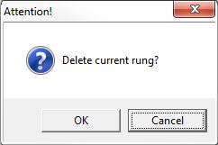
Click the OK button to delete the rung.
Click the Cancel button to close the dialog without deleting the rung.
Cut, Copy, Paste and Delete Entire Rungs
There will be times when building ladder logic programs that complete rungs of ladder logic need to be moved or duplicated within the same code-block, or a different code-block, or even a different project. Do-more Designer provides this functionality by allowing the programmer to select the source rungs and use either a Cut or Copy function within the source code-block, then paste the selected rungs in the destination code-block.
Only entire rungs of ladder logic can be selected, not individual programming elements on a rung.
Before a rung can be selected for a Cut or Copy operation, any changes to the rung must be Accepted.
Selecting a rung of ladder logic also selects the Rung Comment if it exists, so any Cut, Copy, Paste or Delete operation that is performed on a rung will also affect the Rung Comment.
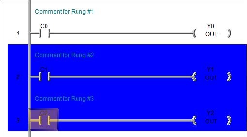
The first step is to select the rungs in the source code-block. This is done by positioning the cursor on the first rung of the selection then use the appropriate keystroke sequence as described below. Each rung that is selected is highlighted with a different background color.
Select Up ( Shft + Up Arrow or Shft + Left Arrow ) - selects rungs upward (backward) through the code-block. The first time the key combination is pressed the current rung is selected. Each successive use adds the previous rung to the selection.
Select Down ( Shft + Down Arrow or Shft + Right Arrow ) - selects rungs downward (forward) through the code-block. The first time the key combination is pressed the current rung is selected. Each successive use adds the next rung to the selection.
Select Home ( Ctrl + Shft + Home ) - selects all of the rungs from the current rung to the beginning of the code-block.
Select End ( Ctrl + Shft + End ) - selects all of the rungs from the current rung to the end of the code-block.
The following example shows rungs numbers 2 and 3 have been selected:
After selecting the rungs, choose one of the following operations to perform on the selection:.
Delete - Pressing the Delete key will remove the selected rungs from the code-block. The Delete operation does not place the deleted contents into the Clipboard. To restore accidentally deleted rungs the programmer must use the Undo (Edit History / Ctrl + Z) feature.
Cut ( Ctrl + X ) - the currently selected rungs will be copied to the Clipboard, then the selected rungs are deleted from the code-block. The Paste operation can now be used to move the selected rungs to one or more different locations. If you wish to copy the original selection without deleting it, use the Copy command.
Copy ( Ctrl + C ) - the currently selected rungs will be copied to the Clipboard. The Paste operation can now be used to duplicate the selected rungs in one or more different locations. If you wish to delete the original selection after copying it, use the Cut command.
Paste ( Ctrl + V ) - will place a copy the rungs of ladder logic currently in the Clipboard at the location of the Edit cursor. To use the Cut / Copy / Paste operation between projects, open a second instance of Do-more Designer, open the second project, and enable Edit Mode. If a new selection has been made, the Paste operation will overwrite the rungs that are currently selected. Otherwise, if there is nothing selected, paste inserts before the cursor.
When pasting the Clipboard contents into a different Do-more Designer project, the Paste Options dialog box will be displayed where the programmer can specify how to handle the Element Documentation in the selected rungs.
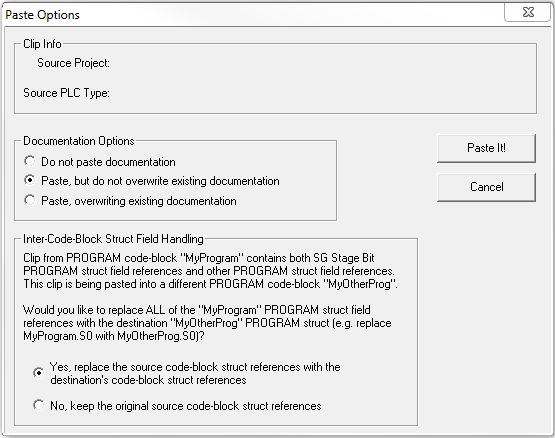
Clip Info - shows where the clipboard contents were copied from
Source Project - the path name of the Do-more Designer project where the rungs were copied from
Source PLC Type - the part number of the Do-more CPU that was selected as the target CPU for the project
Documentation Options - specifies how to handle documentation from the clipboard
Don't paste documentation - pastes only rungs and rung comments. It does NOT paste documentation for the elements in the rungs. See notes below on nicknames.
Paste, but don't overwrite existing documentation - (the default selection) pastes rungs and any rung comments, and documentation for elements in the rungs which have no documentation in the target project. Existing documentation in the project is not changed. See notes below on nicknames.
Paste, overwriting existing documentation - pastes rungs and any rung comments, and documentation for each element used in the pasted rungs. If the target project already had documentation for the elements in the pasted rungs, it will be overwritten. See notes below on nicknames.
Inter-Code-Block Struct Field Handling - specifies what to do with programming elements in the code-block that reference the code-block structure.
For example, assume the source code-block is named MyProgram and the Destination code-block is named MyOtherProgram. MyProgram contains instructions that reference MyProgram.S0, MyProgram.Timeslice, and MyProgram.Done. This dialog gives provides the option to change all of the references to MyOtherProgram.S0, MyOtherProgram.TimeSlice and MyOtherProgram.Done name as part of the paste operation.
Yes, replace the source code-block's struct references with the destination code-block struct references - all references to the source code-block structure members will be changed to the destination code-block structure name.
No, keep the original source code-block struct references - none of the references to the source code-block structure members will be changed.
Click the Paste
It! button to perform the Paste operation.
Click the Cancel button to cancel
the Paste operation.
Note: If there are unassigned nicknames in the rungs that will be pasted, that documentation will always be pasted. The Documentation Option you select above has no affect on them.
All Nicknames must be unique within a project, so, if the Clipboard contains a programming element with a Nickname that already exists in the target project, AND the two Nicknames are tied to two different programming elements, the pasted Nickname will be modified to guarantee uniqueness. The nickname being pasted will have an underscore inserted as its first character. If that does not make it unique, a number will be appended to the end of the nickname, that number will be incremented until a unique Nickname is formed.
When all of the issues that will arise during the paste operation can be handled, the Continue Paste Operation will display list of the changes that will be made to make the paste operation work. Click the OKbutton to complete the paste operation, or click the Cancel button to abort without performing the paste operation.
Note: if there is even one issue that can't be handled automatically, the only option is to Cancel the paste operation.
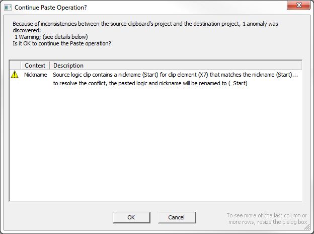
In the above example, the element X0 with the Nickname "Start" is being pasted into a project that already has an element X7 with the Nickname "Start". The Nickname for the pasted element will be changed to "_Start", if _Start already existed, a 1 would be appended to form "_Start1", if "_Start1" existed the 1 would be changed to a 2 to form "_Start2" etc. until a unique Nickname is formed.
Click the OK button to perform the Paste operation.
Click the Cancel button to
cancel the Paste operation.
How To Merge Multiple Rungs into a Single Rung
There may be times during editing sessions when the ladder logic on two adjacent rungs need to be combined into a single rung. One way to accomplish this is to edit one rung and manually add all of the needed ladder logic from the adjacent rung, manually copy / paste the rung comment text from the adjacent rung, and then delete the adjacent rung. A better way is to use the Merge feature to combine the ladder logic and the Rung Comments on two adjacent rungs into a single rung.
Position the Edit cursor on one of the rungs to merge, then select the appropriate Merge selection from the Edit menu:
Edit -> Merge -> Previous Rung - merge the previous rung and it's rung comment with the current rung and it's rung comment.
Edit -> Merge -> Next Rung - merge the current rung with its rung comment with the next previous rung and it's rung comment.
At this point, if you haven't Accepted the merged rungs, you can use the Edit History feature to restore the original rungs along with their individual rung comments.
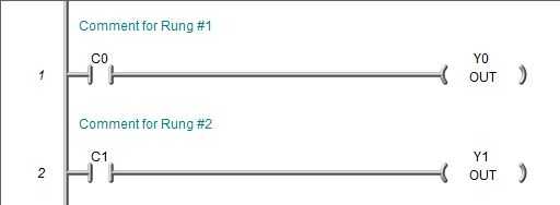
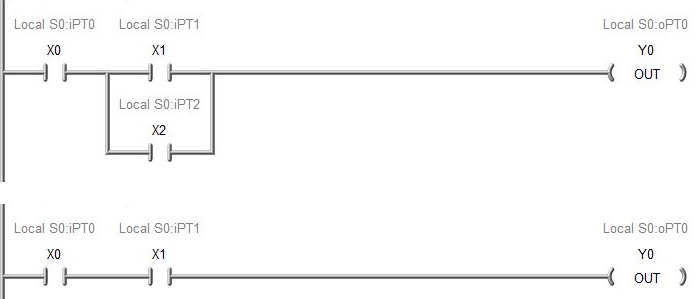
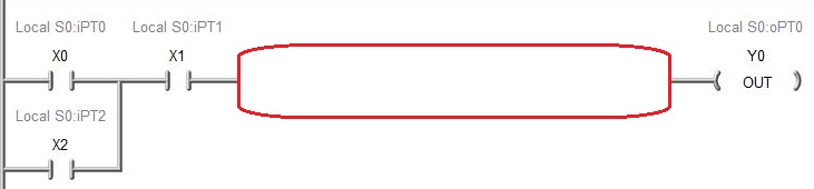
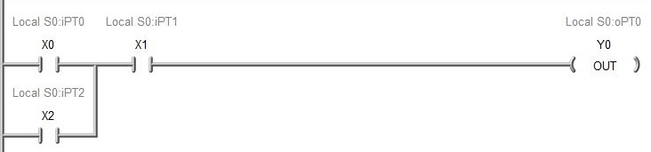
This example shows two simple rungs before being merged:
This is the same two rungs after being merged:
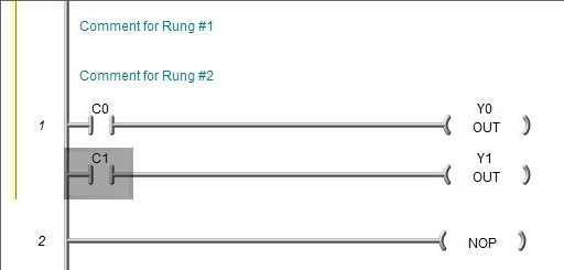
Notice that both rungs of ladder logic are now at Rung #1, and the text from both Rung Comments are now in the comment for Rung #1, and that a yellow Changed Bar is displayed at the left edge, and that Rung #2 is now empty. At this point the programming elements on this new rung can be manually rearranged and the Rung Comment text can be manually edited.
Accept Changes
Any changes that are made to the contents of a code-block must be accepted before they can be downloaded to the PLC. The Accept operation will optimize the way that rungs are drawn - only valid rungs will be optimized, invalid rungs will not be changed. As noted above, any rungs that have been changed will be flagged with a Yellow change bar.
Once the rungs are accepted with no errors, the yellow bar will go away and a green bar will appear indicating the Displayed version of the project has not been saved to disk. If the programming session is online, a cyan bar will also appear, indicating the displayed version of the project has not been saved to the PLC..
Note: Accepting Changes is not selected for individual code-blocks, meaning that if there are multiple code-blocks that have been changed an Accept operation will be applied to all of the currently open code blocks.
Compiler Errors
A part of optimizing a rung is checking the rung for programming elements: what follows is a list of the common compiler error and how to resolve them.
ORing too complex input-output rungs.
Problem: This message is displayed for a rung that contains additional input logic on a leg of a midline output that is illegal. After the vertical wire has been dropped to AND a sub-rung with a midline output, no additional input logic may appear on each leg of the midline output.
Solution: Edit the rung and re-enter all of the common logic in each leg that had additional input logic. This will create additional rungs, but they will be logically equivalent to the original rung.
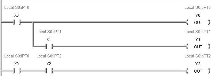
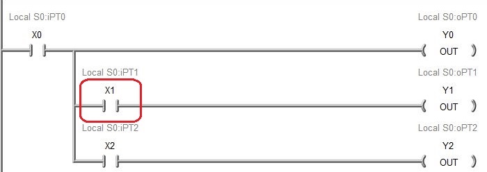
Problem: This message is displayed if the input logic contains a path that allows power to flow from right to left (backwards) through the rung. In the example below, if X1, X2, and X4 are ON, and X3 is OFF, power can flow backwards through X2 and flow forward through X1 to energize Y0.
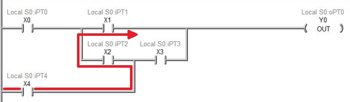
Solution: Edit the rung and duplicate the X3 contact in series with X4, then connect that branch as shown.
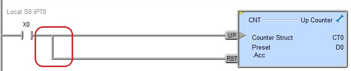
Network contains a short circuit.
Problem: This message is displayed if the rung contains a short circuit, that is, a wired connection with no interposing logic.
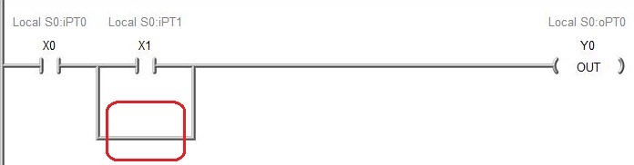
Solution: Edit the rung and either add a logic element to the branch, or delete the wire.
Missing Connection to Power Rail
Problem: This message is displayed when a rung is not connected to the left (power) rail.
Solution: Edit the rung and add the required connecting wire from the leftmost input logic to the left (power) rail.
Connection to Power Rail does not exist.
Problem: This message is displayed when a rung is not connected to the left (power) rail.
Solution: Edit the rung and add the required connecting wire from the leftmost input logic to the left (power) rail.
The limit is 250 elements in series.
Too Many Elements in Parallel.
The limit is 250 elements in parallel.
The limit is 250 outputs on a single rung.
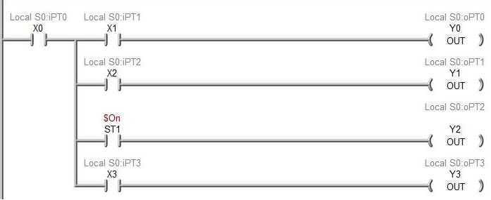
Simple Midline Output in parallel with Contact-driver output; try putting ST1 normally open contact to drive Simple Midline Output
Problem: This message is displayed for a rung that contains input logic on a leg of a midline output that is illegal.
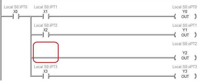
Solution: Edit the rung and add a normally open contact named ST1 ($On); this is logically equivalent to the original rung.
Multiple input box requires each input to be independently tied to the left (power) rail.
Problem: This message is displayed for a rung that contains a box instruction that has multiple inputs legs that have been shorted together. Each input leg of a box must be independently connected to the power rail.
Solution: Connect each input leg independently to the left power rail.
A Powerflow-manipulating instruction is not permitted on a sub-rung.
Problem: This message is displayed for a rung that contains a
Solution: In the example above, replacing the Leading Edge Powerflow Modifier on the sub-rung with Positive Differential instruction.
Standalone output must be the only output on a rung.
Problem: This message is displayed when and a rung contains an output instruction that must exist on it's own rung (e.g. END, RET, NOP) but that rung has other output instructions.
Solution: Move the other instructions to a separate rung so the standalone outputs are the only outputs on that rung.
Inputs are not allowed with an Unconditional Output.
Problem: This message is displayed when a rung contains input logic and an instruction that does not allow input logic.
Solution: Remove the input logic from the rung.
A Conditional Output requires an input instruction.
Problem: This message is displayed for a rung that contains a box instruction that has one of it's inputs directly connected to the power rail.
Solution: Connect each input leg to the left power rail with a ladder logic contact instruction.
Instruction has an invalid parameter.
Problem: This message is displayed for an instruction that has a issue with one of its parameters, or if the instruction itself is not valid for the current PLC.
Rung will cause a stack overflow in the PLC.
Problem: This message is displayed for a rung that contains more instructions than the stack can hold at one time (the stack is 32 levels deep).
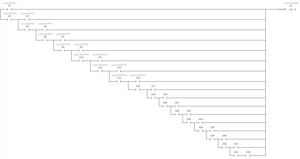
Solution: The example above has 33 input contacts, delete the 33rd contact (for a maximum of 32) and the rung will be valid.
First connection not found for AND operation.
Second connection not found for AND operation.
You should never see these compiler error messages; but if you do contact the technical support at Automationdirect.com for assistance.
See Also:
The Ladder Editor
Related Topics: