Topic: DMD0190

Migrate DirectSOFT Project
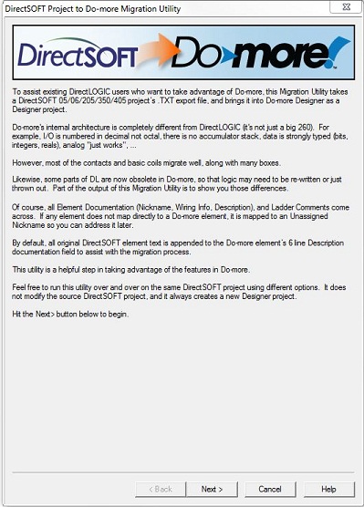
The Migrate DirectSOFT Project utility will assist the programmer in moving a DirectSOFT project that was written for a DirectLOGIC PLC to a Do-more Designer project that will be used in a Do-more CPU. If you want to see a list of how the individual DirectSOFT instructions will be mapped to Do-more Instructions use this link to the DirectLOGIC to Do-More Instruction Map.
This is a migration utility, it is NOT a conversion utility. This is because there are some programming elements in DirectSOFT projects for DL CPUs that are not available in a Do-more CPU, or not required in a Do-more CPU.
Many of the program elements in the DirectSOFT project - like contacts, coils, timer, counters, shift registers - that require only that the memory or I/O references be remapped; these will be moved across to the Do-more Designer project with minimal effort. But there are many programming elements and registers that have no equivalents in Do-more, and these must be handled differently. A good example are the various math instructions that are not required in the Do-more project at all. DirectLOGIC CPU would use a sequences of individual arithmetic instructions to perform math operations whereas a Do-more CPU would use a single MATH instruction where all of the arithmetic operations are performed.
Any issue that cannot be handled automatically by the migration tool will be stored in the Do-more project in the form of DirectLOGIC Stub instructions ($DL, $DL1, and $DLBLK). They will need to be manually replaced with appropriate Do-more ladder logic instructions then deleted from the Do-more project before the project can be downloaded to a Do-more CPU.
I/O and memory references that do not have an equivalent in a Do-more CPU will be migrated into Unassigned Nicknames. These too must be resolved or removed from the project before the project can be downloaded to a Do-more CPU.
The source project can be a DirectSOFT 4, DirectSOFT 5, or DirectSOFT 6 project, for
any of the following Automationdirect CPUs:
-
D0-05, D0-06
-
F1-130
-
D2-230, D2-240, D2-250, D2-250-1, D2-260, D2-262
-
D3-350 ... projects for Automationdirect D3-330, D3-330P, and D3-340 CPUs (and the GE Series One, TI 305 Series, and Siemens 305 Series variants) can not be migrated to a Do-more project. They must be converted manually.
The destination project can be targeted for any of the following CPUs:
Do-more BRX Series ( BX-DM1, BX-DM1E )
Do-more H2 Series ( H2-DM1, H2-DM1E )
Do-more Terminator Series ( T1H-DM1, T1H-DM1E )
Use the File -> Import -> Migrate DirectSOFT Project menu selection to open the migration wizard and start the process.
The migration process uses a DirectSOFT project that has been exported to a text file. If you already have an exported copy of the DirectSOFT project, skip ahead to the sections dealing with mapping.
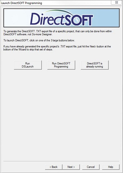
Create the DirectSOFT Export File
- Clicking the Run DSLaunch,
the Run DirectSOFT Programming,
or the DirectSOFT is already running
button to locate and run the most up-to-date version of DirectSOFT software
on the PC.
- Once DirectSOFT Programming is running, open the project to be migrated.
- Select File -> Export -> Program from the menu. Choose a name for the exported file. The default selections for the export options are sufficient for the migration process. Note: make sure the Expand I-Boxes option is NOT selected.
- Click OK to perform the Export.
- Once the export process is complete, close DirectSOFT and return to the Migrate DirectSOFT Project wizard.
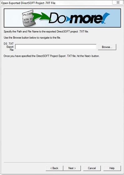
Open the DirectSOFT Export File
Click the Browse button to locate the folder where the Export file is located and highlight the file to be used, then click Open.
Remapping Options
The next five sections of the migration process which deals with how the I/O and memory references will be re-mapped during the migration process. As stated before, some parts of these will migrate directly, some will be remapped, and some will not migrate at all and will have to be rewritten.
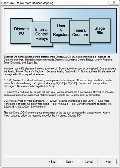
The selection options are similar so make sure to read them closely. As you select the different mapping options, the graphics will change to visually display a simple example of how the remapping would proceed using that option. Because these five section deal with the context of remapping program elements from DirectLOGIC addressing to Do-more addressing, the selection made on the first section will be the default selection for the remaining four sections.
Handling I/O Module Mapping
Discrete I/O Module Mapping
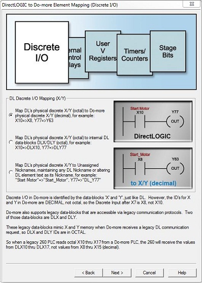
Both the DirectLOGIC and Do-more CPUs use X and Y memory for Discrete Input and Discrete Output modules, X and Y memory in DirectLOGIC PLCs is numbered in octal, whereas the default numbering in Do-more is decimal.
The migration utility provides three options for dealing with this:
-
Map DirectLOGIC X/Y (octal) to Do-more X/Y (decimal), (default) - this option will map all of the octal X and Y references to their decimal equivalents. If they exist, Nicknames, Wiring Info, and Descriptions will follow the element reference.
Refer to the following examples:
DirectLOGIC X0 will be mapped to Do-more X0
...
DirectLOGIC X7 will be mapped to Do-more X7
DirectLOGIC X10 will be mapped to Do-more X8
DirectLOGIC X11 will be mapped to Do-more X9
...
DirectLOGIC X77 will be mapped to Do-more X63
DirectLOGIC X100 will be mapped to Do-more X64
DirectLOGIC X101 will be mapped to Do-more X65
...
DirectLOGIC X377 will be mapped to Do-more X255
-
Map DirectLOGIC X/Y (octal) to Do-more DLX/DLY (octal) - Do-more CPUs are preconfigured with two octal-numbered memory ranges (DLX and DLY) for use by external devices communicating with K-Sequence device drivers. Selecting this option will map all of the octal X and Y references to the same octal references in DLX and DLY memory. If they exist, Nicknames, Wiring Info, and Descriptions will follow the element reference.
Refer to the following examples:
DirectLOGIC X0 will be mapped to Do-more DLX0
...
DirectLOGIC X7 will be mapped to Do-more DLX7
DirectLOGIC X10 will be mapped to Do-more DLX10
...
DirectLOGIC X77 will be mapped to Do-more DLX77
DirectLOGIC X100 will be mapped to Do-more DLX100
...
DirectLOGIC X377 will be mapped to Do-more DLX377
-
Map DirectLOGIC X/Y (octal) to Unassigned Nicknames - this option will NOT map any of the octal X and Y references to physical input or output memory; instead, Unassigned Nicknames will be used for all X and Y references. All Unassigned Nicknames will have to be resolved or removed before the Do-more Project can be downloaded to a Do-more CPU.
-
If the X or Y reference in the DirectLOGIC project has a Nickname, ONLY the Nickname (and If they exist, Wiring Info, and Descriptions) will be maintained, the element reference will NOT be migrated
-
If the X or Y reference in the DirectLOGIC project does NOT have a Nickname, an Unassigned Nickname will be created using the X or Y element reference with a preceding "DL_".
Refer to the following examples:
all references to X0 will be changed to Unassigned Nickname "DL_X0"
all references to X7 will be changed to Unassigned Nickname "DL_X7"
...
all references to X10 will be changed to Unassigned Nickname "DL_X10"
all references to X11 will be changed to Unassigned Nickname "DL_X11"
all references to X100 with Nickname 'Start_Motor' will be mapped to an Unassigned Nickname 'Start_Motor' and the Description field will have 'X100' appended
Analog I/O Module Mapping
Analog I/O Modules in DirectLOGIC PLCs are mapped into Discrete I/O memory. They then use ladder logic to generate the analog input values and store these values in User V-Memory. Ladder logic is also used to retrieve values from User V-Memory and generate the required data for Analog Output modules. Depending on the DirectLOGIC PLC used in the project, and the analog module being used, this ladder logic will either be multiplexing / de-multiplexing logic, or what is referred to as 'pointer method' ladder logic which references slot-specific locations in System V-Memory. These rungs of logic are not required in a Do-more project and will need to be removed before the project can be downloaded to a Do-more CPU.
Do-more CPUs do not require any ladder logic to handle the analog I/O modules like the DirectLOGIC CPUs. Refer to the help topic on Analog I/O Module Mapping to see the I/O map required for each part number.
Analog
Input modules are automatically mapped into WX memory (and
X memory for error reporting). Each WX memory location is a Signed Word (16 bits).
Analog output modules are automatically mapped into WY memory (and Y memory for configuration as required). Each WY memory location is a Signed Word (16 bits).
Because raw analog values are typically not a convenient form for human use, the project most likely contains additional ladder logic that is converting these raw values to engineering units for use in the project. The math operations on these rungs of ladder logic can be replaced with Scale Value (SCALE) instructions. To complete the process, also consider placing the SCALE instructions for Analog Input Modules in the $tTopOfScan System Code block, and placing the SCALE instructions for Analog Output Modules in the $tBottomOfScan System Code block.
Handling Control Relay Mapping
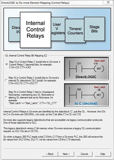
Both DirectLOGIC CPUs and Do-more CPUs use provide C memory for general purpose Control Relays. C memory in DirectLOGIC PLCs is numbered in octal, whereas the default numbering in Do-more is decimal.
-
Map DirectLOGIC Control Relay (octal) to Do-more Control Relay (decimal) - this option will map all of the octal C references to their decimal equivalents. If they exist, Nicknames, Wiring Info, and Descriptions will follow the element reference.
Refer to the following examples:
DirectLOGIC C0 will be mapped to Do-more C0
...
DirectLOGIC C7 will be mapped to Do-more C7
DirectLOGIC C10 will be mapped to Do-more C8
DirectLOGIC C11 will be mapped to Do-more C9
...
DirectLOGIC C77 will be mapped to Do-more C63
DirectLOGIC C100 will be mapped to Do-more C64
DirectLOGIC C101 will be mapped to Do-more C65
...
DirectLOGIC C377 will be mapped to Do-more C255
-
Map DirectLOGIC C (octal) to Do-more DLC (octal) - Do-more CPUs are preconfigured with an octal-numbered memory range (DLC) for use by external devices communicating with K-Sequence device drivers. Selecting this option will map all of the octal C references to the same octal references in DLC memory. If they exist, Nicknames, Wiring Info, and Descriptions will follow the element reference.
Refer to the following examples:
DirectLOGIC C0 will be mapped to Do-more DLC0
...
DirectLOGIC C7 will be mapped to Do-more DLC7
DirectLOGIC C10 will be mapped to Do-more DLC10
...
DirectLOGIC C77 will be mapped to Do-more DLC77
DirectLOGIC C100 will be mapped to Do-more DLC100
...
DirectLOGIC C377 will be mapped to Do-more DLC377
-
Map DirectLOGIC C (octal) to Unassigned Nicknames - this option will NOT map any of the octal C references to Do-more memory; instead, Unassigned Nicknames will be used for all C references. All Unassigned Nicknames will have to be resolved or removed before the Do-more Project can be downloaded to a Do-more CPU.
-
If the C reference in the DirectLOGIC project has a Nickname, ONLY the Nickname (and If they exist, Wiring Info, and Descriptions) will be maintained, the element reference will NOT be migrated
-
If the C reference in the DirectLOGIC project does NOT have a Nickname, an Unassigned Nickname will be created using the C element reference with a preceding "DL_".
Refer to the following examples:
all references to C0 will be changed to Unassigned Nickname "DL_C0"
all references to C7 will be changed to Unassigned Nickname "DL_C7"
...
all references to C10 will be changed to Unassigned Nickname "DL_C10"
all references to C11 will be changed to Unassigned Nickname "DL_C11"
all references to C100 with Nickname 'Start_Motor' will be mapped to an Unassigned Nickname 'Start_Motor' and the Description field will have 'C100' appended
Handling User V Memory Mapping
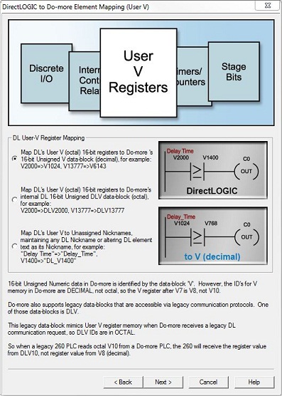
Both DirectLOGIC CPUs and Do-more CPUs use provide V-Memory for general purpose, Unsigned Word (16-bit) registers. V-Memory in DirectLOGIC PLCs is numbered in octal, whereas the default numbering in Do-more is decimal.
DirectLOGIC CPUs have additional sections of 16-bit register locations (System V-Memory, Timer/Counter memory, etc) that are used for configuration and status reporting. References to these V-Memory locations can not be migrated because they have no corresponding function in a Do-more CPU. References to these locations will always be migrated as Unassigned Nicknames, and any ladder logic that has references to these location will need to be removed.
-
Map DirectLOGIC User V (octal) to Do-more V (decimal) - this option will map all of the octal V references to their decimal equivalents. If they exist, Nicknames, Wiring Info, and Descriptions will follow the element reference.
Refer to the following examples:
DirectLOGIC V2000 will be mapped to Do-more V1024
...
DirectLOGIC V2007 will be mapped to Do-more V1031
DirectLOGIC V2010 will be mapped to Do-more V1032
DirectLOGIC V2011 will be mapped to Do-more V1033
...
DirectLOGIC V2077 will be mapped to Do-more V1087
DirectLOGIC V2100 will be mapped to Do-more V1088
DirectLOGIC V2101 will be mapped to Do-more V1089
...
DirectLOGIC V37777 will be mapped to Do-more V16383
-
Map DirectLOGIC V (octal) to Do-more DLV (octal) - Do-more CPUs are preconfigured with an octal-numbered memory range (DLV) for use by external devices communicating with K-Sequence device drivers. Selecting this option will map all of the octal V references to the same octal references in DLV memory. If they exist, Nicknames, Wiring Info, and Descriptions will follow the element reference.
Refer to the following examples:
DirectLOGIC V2000 will be mapped to Do-more DLV2000
...
DirectLOGIC V2007 will be mapped to Do-more DLV2007
DirectLOGIC V2010 will be mapped to Do-more DLV2010
...
DirectLOGIC V2077 will be mapped to Do-more DLV2077
DirectLOGIC V2100 will be mapped to Do-more DLV2100
...
DirectLOGIC V37777 will be mapped to Do-more DLV37777
-
Map DirectLOGIC V (octal) to Unassigned Nicknames - this option will NOT map any of the octal V references to Do-more memory; instead, Unassigned Nicknames will be used for all V references. All Unassigned Nicknames will have to be resolved or removed before the Do-more Project can be downloaded to a Do-more CPU.
-
If the V reference in the DirectLOGIC project has a Nickname, ONLY the Nickname (and If they exist, Wiring Info, and Descriptions) will be maintained, the element reference will NOT be migrated
-
If the V reference in the DirectLOGIC project does NOT have a Nickname, an Unassigned Nickname will be created using the V memory element reference with a preceding "DL_".
Refer to the following examples:
all references to V0 will be changed to Unassigned Nickname "DL_V0"
all references to V7 will be changed to Unassigned Nickname "DL_V7"
...
all references to V10 will be changed to Unassigned Nickname "DL_V10"
all references to V11 will be changed to Unassigned Nickname "DL_V11"
all references to V100 with Nickname 'Start_Motor' will be mapped to an
Unassigned Nickname 'Start_Motor' and the Description field will have
'V100' appended
Handling Timer and Counter Mapping
Timers in DirectLOGIC PLCs are numbered in octal from T0 through T377. Timers numbered T0 through T377 use V0 through V377 respectively to store their 16-bit accumulator values. Accumulating Timers numbered T0 through T377 use two successive V-Memory locations per Timer in the range V0 through V777 respectively to store their 32-bit accumulator values.
Counters in DirectLOGIC PLCs are numbered in octal from CT0 through CT377. Counters numbered CT0 through CT377 use V1000 through V1377 respectively to store their 16-bit accumulator values. Up / Down Counters numbered CT0 through CT377 use two successive V-Memory locations per Counter in the range V1000 through V1777 respectively to store their 32-bit accumulator values.
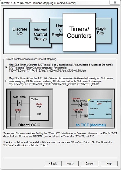
Counters and Timer in Do-more CPUs use structures with appropriate member fields as storage for their status data.
Contacts that reference a Timer or Counter will be migrated as <Timer>.Done or <Counter>.Done.
Relational Contacts that reference a Timer or Counter will be migrated as <Timer>.Acc or <Counter>.Acc.
Other references to Timer current value locations (V0 through V377) will be migrated as <Timer>.Acc.
Other references to Counter current count locations (V1000 through V1377) will be migrated as <Counter>.Acc.
All of the Timers in Do-more PLCs use a millisecond resolution time-base; there are no 'normal - 0.1 second resolution' and 'fast - 0.01 resolution' variants of the Timers. Both Timers and Fast Timers will be migrated into Timer structures. The constant Timer Preset values in the DirectLOGIC project will be converted to milliseconds during the migration process. Any other references to Timer Preset value will have to be manually changed accordingly.
-
Map DirectLOGIC User T / CT (octal) to Do-more Timer / Counter (decimal) - this option will map all of the octal T and CT references to their decimal equivalents. If they exist, Nicknames, Wiring Info, and Descriptions will follow the element reference.
Refer to the following examples:
DirectLOGIC T0 will be mapped to Do-more T0
...
DirectLOGIC T7 will be mapped to Do-more T7
DirectLOGIC T10 will be mapped to Do-more T8
DirectLOGIC T11 will be mapped to Do-more T9
...
DirectLOGIC T77 will be mapped to Do-more T63
DirectLOGIC T100 will be mapped to Do-more T64
DirectLOGIC T101 will be mapped to Do-more T65
...
DirectLOGIC T377 will be mapped to Do-more T255
-
Map DirectLOGIC T / CT (octal) to Unassigned Nicknames - this option will NOT map any of the octal T or CT references to Do-more structures; instead, Unassigned Nicknames will be used for all T or CT references. All Unassigned Nicknames will have to be resolved or removed before the Do-more Project can be downloaded to a Do-more CPU.
-
If the T or CT reference in the DirectLOGIC project has a Nickname, ONLY the Nickname (and If they exist, Wiring Info, and Descriptions) will be maintained, the element reference will NOT be migrated
-
If the T or CT reference in the DirectLOGIC project does NOT have a Nickname, an Unassigned Nickname will be created using the T or CT memory element reference with a preceding "DL_".
Refer to the following examples:
all references to T0 will be changed to Unassigned Nickname "DL_T0"
all references to T7 will be changed to Unassigned Nickname "DL_T7"
...
all references to T10 will be changed to Unassigned Nickname "DL_T10"
all references to T11 will be changed to Unassigned Nickname "DL_T11"
all references to T100 with Nickname 'Motor_On_Time' will be mapped to
an Unassigned Nickname 'Motor_ON_Time' and the Description field will
have '_T100' appended
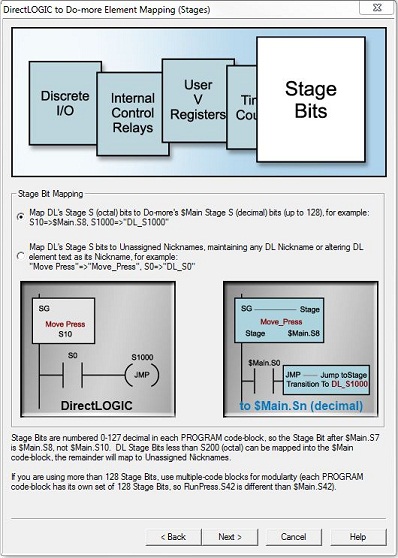
Handling Stage Bit Mapping
Both DirectLOGIC CPUs and Do-more CPUs use provide S memory for Stages. A DirectLOGIC PLC can contain up to 128 Stage instructions which are numbered in octal from S0 through S127.
Each PROGRAM code block in a Do-more PLC can contain up to 128 Stage instructions which are numbered in decimal from <CodeBlockName>.0 through <CodeBlockName>.127.
-
Map DirectLOGIC Stage (octal) to Do-more Stage (decimal) - this option will map Stages numbered S0 through S177 to their decimal equivalents (S0 through S127) in the $Main code block. Stages numbered S200 and above will be Migrated as Unassigned Nicknames. If they exist, Nicknames, Wiring Info, and Descriptions will follow the Stage element reference.
Refer to the following examples:
DirectLOGIC S0 will be mapped to Do-more $Main.S0
...
DirectLOGIC S7 will be mapped to Do-more $Main.S7
DirectLOGIC S10 will be mapped to Do-more $Main.S8
DirectLOGIC S11 will be mapped to Do-more $Main.S9
...
DirectLOGIC S177 will be mapped to Do-more $Main.S127
...
DirectLOGIC S200 will be mapped to Do-more Unassigned Nickname "DL_S200"
DirectLOGIC S1777 will be mapped to Do-more Unassigned Nickname "DL_S1777"
-
Map DirectLOGIC Stage (octal) to Unassigned Nicknames - this option will NOT map any of the octal Stage references to Do-more memory; instead, Unassigned Nicknames will be used for all Stage references. All Unassigned Nicknames will have to be resolved or removed before the Do-more Project can be downloaded to a Do-more CPU.
-
If the Stage reference in the DirectLOGIC project has a Nickname, ONLY the Nickname (and If they exist, Wiring Info, and Descriptions) will be maintained, the element reference will NOT be migrated
-
If the Stage reference in the DirectLOGIC project does NOT have a Nickname, an Unassigned Nickname will be created using the Stage memory element reference with a preceding "DL_".
Refer to the following examples:
all references to S0 will be changed to Unassigned Nickname "DL_S0"
all references to S7 will be changed to Unassigned Nickname "DL_S7"
...
all references to S10 will be changed to Unassigned Nickname "DL_S10"
all references to S11 will be changed to Unassigned Nickname "DL_S11"
all references to S100 with Nickname 'Motor_Control' will be mapped to
an Unassigned Nickname 'Motor_Control' and the Description field will
have 'S100' appended
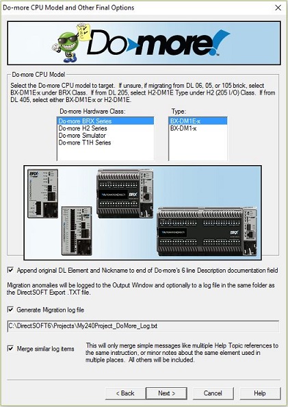
Select the Target Do-more CPU
Use the Do-more Hardware Class and the Type selections to specify the Target Do-more CPU. The CPU type for a Do-more Designer project can be changed later using the Setup Offline CPU utility.
If the DirectSOFT project was written for a DL05, DL06, or DL105 CPU you should select, the most appropriate selection would be one of the BRX CPUs.
If the DirectSOFT project was written for one of the DL205 or DL405 CPUs you should select the Do-more H2 Series and H2-DM1E CPU as this selection will match the widest range of I/O configurations of the original DirectSOFT project.
Migration Process Log File
Append Original DirectLOGIC Element and Nickname to Do-more Description
By default, the Element (for example V0, X37, C2000 ) and the Nickname (if one exists) will be appended to the Description text in the Do-more project. Because of the octal-to-decimal numbering conversion that occurs as part of the migration process this is very useful as it will let you know where the Element or I/O point was originally mapped to in the DirectSOFT project. You will most likely want to delete this information from the Description field after you've completed the migration.
Generate migration log file
By default, the migration process creates a log file (called <Project_Name>_DoMore_Log.Txt in the folder where the DirectSOFT export file is located). This file will contain all of the status information generated during the migration process, which will prove invaluable during the remaining portions of the migration.
Merge similar log items
A typical DirectSOFT project will contain many instances of the same instructions and memory references that cannot be automatically migrated to an equivalent Do-more instruction or memory reference. Each instance will be noted by the migration process and this selection will specify how to handle reporting the multiple instances.
Enabled (default) will generate a single entry in the log file for multiple references to a single message item regardless of how many times it appears in the DirectSOFT project.
Disabled will generate an entry in the log file for each and every instance of a message.
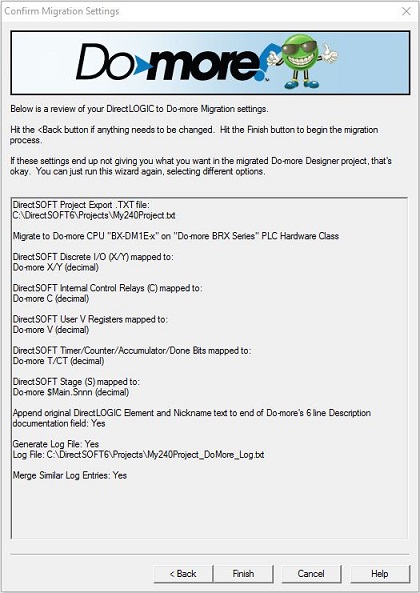
Review Migration Selections
This step will display the migration settings you've specified in the previous steps. Review them and either click Back to return to a previous step so that the setting can be changed, or click Finish which will begin migrating the project.
The Migrate operation is a multiple-pass process which begins with creating a new, offline Do-more Designer project for the target Do-more CPU specified in the previous step. The migration process steps through each programming element on each rung of the ladder logic, processing each element the mapping selections specified on the initial dialog. As each element is processed, any status messages or error messages will be displayed in the Output Window.
If the option was enabled, the migration process will create a log file (named <Export_Filename>_DoMore_Log.Txt in the folder where the export file is located). This file will contain all of the status information generated in the Output Window during the migration process, which will prove invaluable during the remaining portions of the migration.
When the migration process has successfully completed, the following message box is displayed:
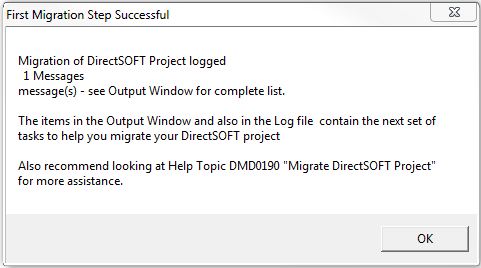
Click OK to finish the migration process and view the Do-more Designer project that was created.
Once the Do-more Designer project is opened, the following will prompt you to open the log file created during the migration process.
Manually Completing the Migration
The automatic portion of the migration process will generate a valid Do-more Designer project that contains the ladder logic rungs and programming elements. The migration process will typically not be able to automatically process all of the elements in a DirectSOFT project, meaning that most project migration efforts will require additional manual editing to complete the process.
What follows are some general guidelines to follow to get the manual
portion completed as quickly as possible. The required manual editing
will be an iterative process as you step through each of the issues detailed
in the log file. To get through the required work you will need:
-
the original source DirectSOFT project
-
the log file created during the migration process (named <Export_Filename>_DoMore_Log.Txt in the folder where the DirectSOFT export file was located)
-
the newly created Do-more Designer project
-
if you have the Do-more CPU and I/O Module hardware, make a communication link to the CPU and establish an online session.
If you do not have the Do-more CPU and the I/O Modules, then use the Manual configuration option in the I/O Configuration section of the System Configuration to manually enter the I/O layout of the I/O Modules in the system that will ultimately be used.
Either of these options will establish the I/O portion of the System Configuration which will have the I/O Mapping information in place and will have Module Configurations for any of the I/O modules that require them.
Complete the I/O Module Mapping
Discrete Input and Output
Modules
Remember that Do-more CPUs use decimal addresses for I/O instead of octal.
This link to the help topic on Mapping for Discrete Input and Output Modules details the I/O footprint for each Discrete Input and Output module by part number.
All references to GX, GY will be mapped to Unassigned Nicknames and will have to be resolved or removed before the project can be downloaded to a Do-more CPU.
Analog Input and Output
Modules
Remove rungs that are used to setup the pointer method or multiplexing code. They are not needed because Do-more automatically maps analog inputs into WX memory and analog outputs into WY memory.
This link to the help topic on Mapping for Analog Input and Output Modules details the I/O footprint for each Analog Input and Output module by part number. It also denotes which modules use Module Configurations for initial setup and / or runtime configuration, and how each module handles runtime error reporting (if applicable).
Take note of any rungs that are converting raw analog input values to engineering units, or converting engineering units to raw analog output values. These rungs can be easily converted to use Scale Value (SCALE) instructions.
Take note of any ladder logic that is monitoring errors from analog input modules. Use the link to the aforementioned help topic for information on how these error conditions are reported in a Do-more CPU and make the required changes to the ladder logic.
Do-more Designer does not use CTRIO Workbench to configure the H2-CTRIO, H2-CTRIO2 or T1H-CTRIO modules, they are configured in CTRIO Module Configuration section of the System Configuration.
The Module Configuration can import existing CTRIO configurations from CTRIO Workbench (.CWB) files.
Any ladder logic or I-Box instructions use to run the CTRIO module will need to be replaced with Do-more CTRIO instructions.
Use the PLC -> PLC -> Monitor CTRIO Module utility to interact with the CTRIO/2 modules at runtime.
Complete the Communications with External Devices
Do-more uses a device driver to manage onboard communication ports and the ports on communication modules.
DirectSOFT Communication I-Box instructions will generally migrate well, but ladder logic that uses the traditional "LD / LD / LDA / RX " instruction sequence will not migrate as a single Do-more communication instruction.
DirectLOGIC PLCs use the 'Port Busy' SP control relay in the ladder program to interlock any RX or WX communication requests that target the same communication port. That interlocking logic is not required in a Do-more instruction because the device driver that manages the communication port provides all of the required interlocking internally.
Do-more CPUs provide Modbus and K-Sequence Server support for external client devices using Modbus and K-Sequence protocol respectively. Read and Write operations from these external client devices will only have access to areas of memory that Do-more CPUs allocate for use by each protocol.
External Modbus/TCP and Modbus/RTU clients will only have access to MI (Modbus Input), MC (Modbus Coil), MIR (Modbus Input Register) and MHR (Modbus Holding Register) memory locations.
External K-Sequence clients will only have access to DLX (DirectLOGIC Input), DLY (DirectLOGIC Output), DLC (DirectLOGIC Control Relay), DLV (DirectLOGIC Register) memory locations.
Note: refer to the Help topic on the Built-in Data Blocks for information on the External Communication memory ranges in a Do-more CPU.
Resolve $DL, $DL1, and $DLBLK (DirectLOGIC Stub) instructions
All of the $DL, $DL1 and $DLBLK instructions
will have to be manually processed. They will need to be replaced with
the appropriate ladder logic instructions then deleted from the Do-more
project and before the project can be downloaded to a Do-more CPU. These
instructions will contain three string entries:
-
the first entry shows the original instruction mnemonic element from the DirectSOFT project that can't be processed
-
the second entry will have one of the following:
-
a Do-more instruction that is similar in function with a description of how to use it
-
"n/a" if there is no equivalent function in a Do-more CPU
-
"n/a" if the function is not required by a Do-more CPU
-
the third entry will be text with additional information on how to proceed with the contents of this DirectLOGIC Stub instruction.
Note: refer to the Help topic for the Instruction Set for a complete list of the instructions available for use in a Do-more CPU.
Most of the DL SP (Special Purpose) Bits do not map into Do-more ST (Status) bits because those functions are not required in Do-more. They will be mapped to Unassigned Nicknames which must be resolved or removed from the project.
Note: refer to the Help topic on the System Nicknamed Bit Locations for a list of Bit locations in a Do-more CPU that have a System-Assigned Nickname.
All references to System Variable Memory locations are mapped to Unassigned Nicknames because most of them are not required in Do-more.
They must be resolved or removed from the project.
Note: refer to the Help topic on the System Nicknamed DWord Locations for a list of DWord locations in a Do-more CPU that have a System-Assigned Nickname.
Arithmetic operations (Add, Subtract, Multiply, Divide, etc.) in DirectLOGIC PLCs are done with sequences of stack-based instructions. Do-more CPUs use a single MATH - Calculate Expression instruction to perform all arithmetic operations. The native numeric format for arithmetic operations (Add, Subtract, Multiply, Divide, etc.) in DirectLOGIC PLCs is BCD (unless expressly converted to a different format with ladder logic instructions). Do-more CPUs use decimal (aka binary) and Real as the native numeric format. Any ladder logic that is performing arithmetic calculations will need to be checked to make sure the numeric format used will generate the correct result.
Do-more uses array references for indirect addressing - like D[ V0 ], where V0 contains the index number from 0 to 65535. DirectLOGIC PLCs used the P memory type - like P2000, where the contents of V2000 is interpreted as an Octal V-Memory address. Any references to P memory will be mapped to Unassigned Nicknames and must be resolved or removed from the project.
Do-more uses Date / Time structures and Date / Time instructions for runtime date and time calculations, whereas DirectLOGIC PLCs use a series of System V-Memory locations to hold each component of the clock and calendar information. The ladder logic using these locations must be rewritten to use the $Now Date / Time structures and Date Time instructions. Any references to these locations will be mapped to Unassigned Nicknames and must be resolved or removed from the project.
Note: refer to the Help topic on the Date and Time Overview for information on the Date / Time structures and the Date / Time instructions that use them.
Converting a DirectLOGIC project to a Do-more project is more than simply getting the ladder logic elements, I/O and memory references moved across, that's why at this point the programmer's action is "conversion". Project conversion will typically involve rewriting sections of the ladder logic to take full advantage of doing things the Do-more way.
Take advantage of Do-more's inherent modularity by moving sections of ladder logic into Program or Task code blocks. Some good examples of using the built-in System Tasks are:
Rungs using SP0 (FirstScan) could be moved to $tFirstScan System Task. Also consider using the, Set Range (SETR) / Reset Range (RSTR) and Initialize Data (INIT) instructions if there are several instances of LD & OUT instructions that setting the initial states of discrete elements or setting initial values respectively on the first PLC scan.
Rungs that are scaling analog input values could be moved to $tTopOfScan System Task
Rungs that are scaling analog output values could be moved to $tBottomOfScan System Task
Take further advantage of modularity by moving sections of ladder logic into user-created Program, Task, Subroutine, and Interrupt Service Routine code blocks. Some good examples of doing this are:
If the project contains sections of ladder logic that gets enabled / disabled on an as-needed basis (at specific time intervals or on certain events) consider moving those sections of logic into separate Tasks and adding Enable Task (ENTASK) instructions for each Task code-bock created.
If the project contains sections of ladder logic that needs to handle asynchronous processing, or handle ladder logic that takes multiple scans to complete, consider moving these sections of ladder logic to Program code blocks and add Run Program (RUN) instructions for each Program code-block created.
If the project contains sections of ladder logic that need to be executed multiple times with a different set of input and / or output values each time it is executed, consider putting this section of ladder logic in a Subroutine.
If the project contains sections of ladder logic that need to be executed when external hardware signals are seen, or executed at specific time intervals, consider putting this section of ladder logic in an Interrupt Service Routine (BRX only).
If the project is implementing multiple Stage diagrams consider moving the Stages associated with each diagram into separate Program code blocks and add Run Program (RUN) instructions for each Program code-block created. Also look at each of the DirectLOGIC ISG (Initial Stage) instructions as a possible starting point for a new Program code-block.
If the project contains sections ladder logic that you would prefer to be locked (read-only with password to unlock) move those sections of ladder logic into separate Program code blocks, add Run Program (RUN) instructions for each Program code-block created, then configure those Programs to enable one of the Code-Block Protection schemes.
If the DirectLOGIC system is using an ERM as a remote I/O master for an EBC100 or GS-EDRV100, you should consider removing the ERM and using Do-more's built-in Ethernet I/O Master function which can use BX-DMIOs, BX-EBC100s, H2-EBC100s, T1H-EBC100s, and GS-EDRV100s as Ethernet I/O Slaves. The major benefit is that it allows the Do-more CPU to interact with the I/O modules in the EBC100 Slave systems the same as it does with the I/O modules in the local base.
See Also:
Migrate DirectSOFT Project
DirectLOGIC
to Do-More Instruction Map
Related Topics:
Insert Instructions
from a File
Using Cut / Copy / Paste to Move Rungs and Code Blocks