Topic: DMD0239

Project Browser
The Project
Browser is a Dockable![]() A Dockable window is one that can be connected to the sides, top, or bottom of another window.
Docking is done by clicking the mouse in the colored portion of the top bar of the window and dragging it toward the edge of the contain window. As it approaches the containing window, a reverse video block will appear, showing how the docked window will appear in its docked form. and Floatable
A Dockable window is one that can be connected to the sides, top, or bottom of another window.
Docking is done by clicking the mouse in the colored portion of the top bar of the window and dragging it toward the edge of the contain window. As it approaches the containing window, a reverse video block will appear, showing how the docked window will appear in its docked form. and Floatable![]() This window can "float" on the screen and remain functional while being unconnected to an edge of a containing window.
Floating a window is done by clicking the mouse in the colored portion of the top of the window and dragging it away from the edge, As the window is dragged away, a reverse video block will appear, showing how the window will appear in it's floating form. view that uses a tree control to provide
quick navigation to the different areas of a Do-more Designer project . The Project Browser is the also proper place to create and edit the various code-blocks (Programs, Tasks, Subroutines, and Interrupt Service Routines) in a project.
This window can "float" on the screen and remain functional while being unconnected to an edge of a containing window.
Floating a window is done by clicking the mouse in the colored portion of the top of the window and dragging it away from the edge, As the window is dragged away, a reverse video block will appear, showing how the window will appear in it's floating form. view that uses a tree control to provide
quick navigation to the different areas of a Do-more Designer project . The Project Browser is the also proper place to create and edit the various code-blocks (Programs, Tasks, Subroutines, and Interrupt Service Routines) in a project.
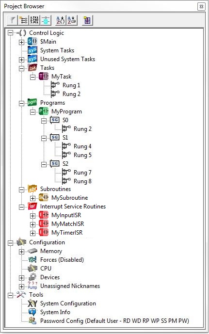
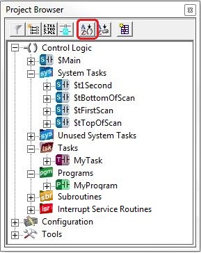
The tree view has the following three root groups:
Control Logic
- lists the Programs and Tasks in the project.
Each Program code-block in
the list can be expanded to show each rung and each Stage (if present)
within each code block.
Each Task code-block in the
list can be expanded to include each rung.
Each Subroutine code-block in the
list can be expanded to include each rung.
Each Interrupt Service Routine code-block in the
list can be expanded to include each rung.
If a rung comment exists
for a Stage or rung, the first line from that rung comment will also be
displayed.
Navigation to a specific
code-block, or to a specific Stage or rung, is done by double-clicking
on that item in the list.
Configuration - lists the Data Blocks, Heap Items, and Devices defined in the current System Configuration.
The Memory sub-section has lists of the Discrete, Analog, & Specialty I/O modules. the System Status Bits, Status Words & Structure Memory, the PEERLINK, DL & Modbus Memory, the User Bit, Numeric & Structure Memory and String Memory
The Forces sub-section has lists of memory locations and I/O points that are forced.
The Devices sub-section has lists of all system-created and user-created Devices.
The Unassigned Nicknames sub-section has lists of any Nicknames that have not been assigned to a controller memory element
The Symbolic Constants sub-section has list of all the constant numeric values that have an assigned Nickname.
Tools - contains links to some of the tools that are most commonly used during programming sessions. The list also displays the currently logged-in user account and the permissions of that account.
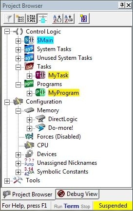
Project Browser Shows Online Status Information
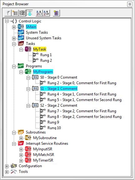
When the Status is turned ON, the Control Logic portion of the Project Browser additionally shows the Enabled / Disabled / Suspended status of each of the Task and Program code-blocks. For Programs that include Stage instructions, there is also Enabled / Disabled status for each Stage in that program.
With Status turned ON:
Code-blocks that are
Enabled (that is, they are part of the current PLC scan) will be displayed with a cyan background. Code-blocks that are disabled will be displayed with a normal background.
Program code-blocks that have Stage instructions will display the Stage instructions that are Enabled will be displayed with a cyan background. Stage instructions that are disabled will be displayed with a normal background.
Code-blocks that are
Suspended will be displayed with a yellow background. Code-blocks that are not suspended will be displayed with a normal background.
Code-blocks that were
Enabled when the controller last made a transition from RUN mode to STOP mode will be displayed with a gray background.
Code-blocks that are locked will display a lock in the graphic to the left of the code-block's name
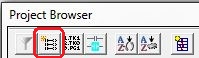
Project Browser Toolbar Buttons
The six buttons across the top of the Project Browser window and the Right-Click menu contain options that define how the Project Browser will display the root groups, their sub-groups, and the lists of data elements found there. A discussion of each button's functionality follows:
Control Logic Filters
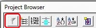
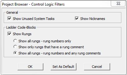
The first button is Filters which opens the Control Logic Filters dialog which defines the following display options:
General
Show Unused System Tasks - if enabled, the Unused System Tasks group and any unused System Tasks in that group will be listed
Show Nicknames - if enabled, if a code-block has been assigned a Nickname, the Nickname will be displayed instead of the code-block name
Show Rungs - if enabled, each code-block can be expanded to show a placeholder for each rung, that will be displayed in one of the following ways:
-
Show All Rungs - rung numbers only - a placeholder is displayed for each rung.
-
Show Only rungs that have a rung comment - a place-holder and the first line of the comment text are displayed only for rungs that have comments.
-
Show All Rungs - rung numbers and any rung comments - (the default setting) - displays a place-holder for each rung and displays the first line of the comment text for each rung that has one.
Click OK to save any changes.
Click Set As Default to save any changes and make these settings apply to future projects.
Click Cancel to exit without saving any changes.
Creating New User Code Blocks
The second button is Create New User Code Block which opens the following dialog which allows the user to begin the process of creating a new code block:

Program - code-blocks that are run by the event-triggered Run Program (RUN) instruction. Programs can be self-terminating or never terminate. Stage programming instructions can only be used inside Program code-blocks.
Task - code blocks that are enabled or disabled using the Enable Task (ENTASK) instruction. The Enable Task (ENTASK) instruction allows the Task to execute while the ENTASK instruction has power-flow, or at intervals specified at millisecond resolution.
Subroutine - subroutines are code-blocks that are invoked through the Call Subroutine (CALL) instruction. All of the ladder logic in a subroutine is executed each time the subroutine is called.
Interrupt Service Routine (ISR) - code blocks that are executed when an Interrupt Trigger occurs on a BRX High-Speed I/O input. Interrupt Triggers are configured within the System Configuration or at runtime using the INTCONFIG - Configure Interrupts instruction.
Click Create to create the new code-block. At this point you will be shown an appropriate series of dialogs where you configure the code-block based on the type selected.
Click Cancel to exit without creating the code-block.
Modifying the Execution Order of Programs and Tasks
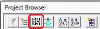
The third button from the left is Modify Execution Order which opens a dialog that allows the user to specify the order that the code-blocks in the project will be executed.
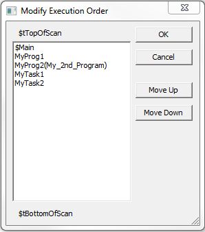
Each code-block in the project whose order can be changed is specified in the list. Nicknames for code-blocks that have them will be displayed in parenthesis.
The execution order of code-blocks that cannot be changed ($tFirstScan, $tLastScan) will not show up in this list. If the System Tasks $tTopOfScan or $tBottomOfScan are used in the project they will be displayed above or below the list respectively.
To modify the execution order click on a Program or Task in the list to highlight it, then click Move Up to make the highlighted code block execute earlier in the scan, or click Move Down to make the highlighted code-block execute later in the scan.
Click OK to save any changes.
Click Cancel to exit without changing the execution order.
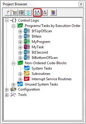
Modifying the Sort Order for Programs and Tasks
The fifth button is Modify Program / Task Sort Order which defines the order in which the Programs and Tasks in the project will be displayed in the Project Browser. Select from the two following options:
Sort by Code-Block Type then Name - (the default) - sorts the list by type (Main, System, Unused System, Tasks, Programs), and sorts by Name within each type.
Sort by Execution Order - sorts the list in the order the Programs and Tasks will be executed during the controller scan.
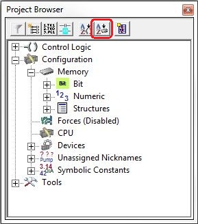
Modifying the Sort Order for Memory Items
The sixth button is Modify Memory Sort Order which defines the order in which the Memory in the project will be displayed in the Project Browser. Using the various sort types can help the programmer quickly find a specific memory element in the list of memory elements available. Select from the following five options:
Sort Memory Items by Data Type - sorts the list of Memory items into three groups: Bit, Numeric, and Structures
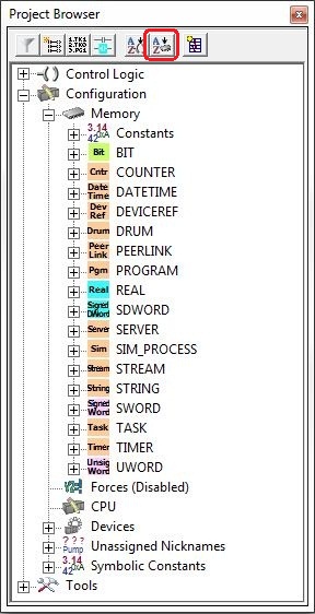
Sort Memory Items by Data Type Alphabetically - sorts the entire list of Memory items by data type then lists the types alphabetically
Sort Memory
Items by Function - (the default) - sorts the list of Memory items
into functional groups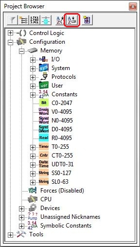
Sort Memory
Items Alphabetically - sorts the list of Memory items alphabetically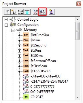
Sort Memory
Items Platform (DirectLOGIC vs. Do-more) - sorts the list of Memory
items into two groups: one for DirectLOGIC-compatible memory items, the
other for Do-more specific memory items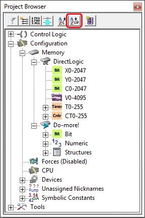
Create a Data Block
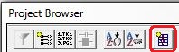
The final button is Create Data Block which opens a dialog that allows you to create a new Data Block for use in the Project. This is essentially the same function as Add Memory Block on the Memory Configuration tab of the System Configuration utility.
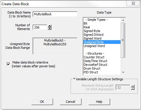
Data Block Name (1 to 16 letters) - Block names must be unique, and consist of 1 to 16 characters (A-Z, a-z; no numbers, no spaces).
Number of Elements - specifies the size of the data block to create. Data blocks must be created on DWord (4-byte boundaries).
Data Type - the type of each element in the data the block.
Simple Types - each element of the data block will be the same type. Select the type from the list.
Structures - each element of the data block will be a structure. Select the type of structure from the list.
Variable Length Structure Settings - if the structure specified is a String Struct, enter the length of each String structure in the data block.
Data Block Range - displays the first and last element of the block that will be created based on the current entries for Data Block Name and Number of Elements.
Make Data Block Retentive (retain values after power loss - a data block marked as retentive will hold its state through a power cycle or a Program-to-Run mode transition. The status of memory NOT marked as retentive will be cleared at power up and during a Program-to-Run mode transition.
Cut / Copy / Paste Code-Blocks
The project browser allows entire code-blocks to be cut or copied, then a copy of that code-block to be pasted into the current project or into a separate project. Keep in mind that using the Cut, Copy, or Paste Code-block operations will change the System Configuration, which can only be downloaded to the controller in Program mode.
Cut - (Right-click -> Cut Code Block,
Ctrl-X) - each Cut Code-block operation will perform the following
actions:
A copy of the currently selected code block is placed in the clipboard.
The currently selected code- block is removed from the project.
The programmer is prompted to remove the Heap Item that is associated with the code-block.
Copy - (Right-click -> Copy Code Block, Ctrl-C) - each Copy Code-block operation will place a copy of the currently selected code block into the clipboard
Paste - (Right-click -> Paste Code Block, Ctrl-X) - each Paste Code-block operation will perform the following actions:
The programmer will be prompted to confirm the creation of the new code-block using the data in the clipboard.
If the name of the code-block already exists in the project, "COPY_" is pre-pended to the first 5 and the last 5 characters of the code-block name (if it’s larger than 10 characters). Additional paste operations will pre-pend "COPYx_" to the code-block name where x is the number 1 through 999. For example, if the code-block in the clipboard is named MyTask, the first paste operation would create "COPY_MyTask", the next paste operation would create COPY1_MyTask, the next paste would create COPY2_MyTask, etc..
Note: after a successful Paste Code-block operation an entry is added to the Output Window that displays the name of the new code-block. To change the name of the newly-pasted code-block double-click the entry in the output Window, or right-click on the code-block in the Project Browser and select Configure Code-Block.
Debug Operations for Code-Blocks
The right-click menu for a code-block has a selection called Debug Code-Block option, which contains a list of debug operations that can be performed on the highlighted code-block:
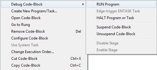
Run Program
Selecting this option will cause the selected Program code-block to Run. It performs the same operation as a Run Program - (RUN) ladder logic instruction.
Edge-Trigger ENTASK Task
Selecting this option will cause the selected Task code-block to execute. It performs the same operation as an Enable Task - (ENTASK) ladder logic instruction that is configured as to be Edge-Triggered. This option can only be used on Tasks that are executed as edge-triggered Tasks. An error message will appear if the selected Task is running recurrently (automatically executing at some interval).
Halt Program or Task
Selecting this option will cause the selected Program to stop running, or Task code-block to stop executing. It performs the same operation as a Halt Program or Task - (HALT) ladder logic instruction.
Suspend Code-Block
All System and User Programs and Tasks can be suspended and unsuspended as required. When a Program or Task is suspended the ladder logic in that code-block is no longer processed. If the code-block was running when the suspend operation was executed, the code-block will remember the last instruction that was executed, and when it is unsuspended, execution will resume with the next instruction.
To suspend a Program or Task, right-click and select Debug Code-Block -> Suspend Code-Block from the popup menu. The Suspend Program or Task (SUSPEND) instruction can also be used to suspend a Program or Task.
With Status turned ON, and the controller in RUN mode, the name of the suspended Program or Task will be displayed with a yellow background in the Project Browser, and the word " Suspended " with yellow background will be displayed on the status bar.
Unsuspend Code-Block
To Unsuspend a Program or Task that has been suspended, right-click and select Debug Code-Block -> Unsuspend Code-Block.
If there are one or more Programs or Tasks that are still Suspended when an attempt to close an online session Do-more Designer session - disconnecting from the controller or closing the project - this warning dialog will be displayed with the following options:
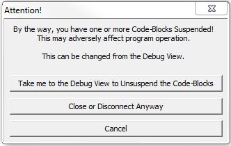
Take me to the Debug View to Unsuspend the Code-Blocks - invokes the Debug View where the suspended code-blocks can be unsuspended.
Close or Disconnect Anyway - close the project or complete the disconnect operation leaving the Programs or Tasks suspended.
Cancel - do not close the project or disconnect from the controller
Disable Stage
Selecting this option will turn OFF the selected Stage in the Program code-block. It performs the same operation as a Disable Stage (SGRST) ladder logic instruction.
Enable Stage
Selecting this option will turn ON the selected Stage in the Program code-block. It performs the same operation as an Enable Stage (SGSET) or Jump to Stage (JMP) ladder logic instruction.
Cross Reference for Code-Blocks
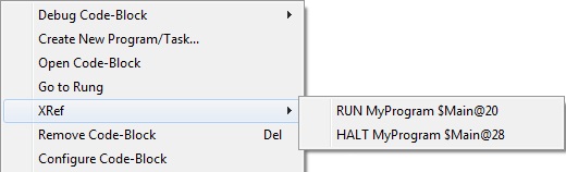
The right-click menu for user-created code-blocks contains an XRef: selection. The selection will show the following:
The instruction that references the code-block: RUN, ENTASK, HALT, etc.
The code-block name.
The address of the instruction that references the code-block: $Main@28.
Selecting one of the cross reference listings will open the code-block (if it's not already open) and place the cursor on that instruction.
Changing the Update Interval for the Project Browser
There are times when the ability to change the default update rate of the various Views in the Do-more Designer programming software is needed. By default, Do-more Designer will generate communication requests at rate that is high enough to present the most current status values for the on-screen elements. But on computers that are CPU-speed-challenged or memory-challenged, maintaining this update rate at the expense of allowing CPU time for other processing can be a problem.
To address this need, Do-more Designer uses two entries in the [SETUP] group of DmDesigner.Ini, named ProgViewInterval & DataViewInterval, to govern the rate at which the individual views will update the status for the elements they contain:
ProgViewInterval applies to Ladder Views, Debug Views, the Module Browser, Data Views, Device Views, PID Overview, etc.. Its value is the rate (in milliseconds) that status communication requests occur for those views. The default for these views is 25ms. If the entry does not exist, or is commented out (like in the example below), the rate will be the 25ms default. This value can be as small (for a fast update), or as large (for a slow update) as desired. A value 0 means "as fast as possible".
DataViewInterval applies only to Data Views. Its value is the frequency (in milliseconds) that status communication requests occur only for Data Views. The default value is 75ms. If both ProgViewInterval & DataViewInterval exist in DmDesigner.Ini, ProgViewInterval will supersede DataViewInterval ONLY if it is SLOWER (i.e. a higher number). If only the ProgViewInterval exists, any Data View will use the slower of that value or the value or 75 (the default for Data Views).
The default condition for both of these entries has them both commented out (as shown below), meaning that all of the views in Do-more Designer will operate at an update rate of 25ms, and on most modern computers with sufficient RAM the default intervals should not cause any issues.
[SETUP]
;ProgViewInterval=25
;DataViewInterval=75
To enable one of these settings, remove the semicolon from the entry and change the update interval to the millisecond value desired.
Note: because Do-more Designer only reads the entries from DmDesigner.Ini when the software is first started, Do-more Designer will need to be closed, then re-opened to put any changes made to DmDesigner.Ini into effect.