Topic: DMD0234

The Do-more Simulator
The Do-more Designer programming environment includes a PC-based, Do-more CPU simulator. This Simulator operates as a Virtual PLC with an Ethernet-equipped CPU and 4 I/O modules. The Do-more Designer software interacts with the Simulator in the same manner as it would a 'real' Do-more CPU, for example, an online session is established through an automatically-created Ethernet communication link called MySim.
The Simulator has a default System Configuration and a default Memory Configuration that can be changed as required. The I/O Configuration is fixed.
Do-more Designer projects are downloaded to the Simulator just as they would be to an actual Do-more CPU. Putting the Simulator in RUN mode will cause it to execute the ladder logic in the project. The Simulator will stay in RUN mode for a maximum of 1 hour before automatically reverting to PROGRAM mode.
When you first open a project for the Simulator, a disk file named DmSim.Dat is created that provides the RAM and ROM storage for the simulator. Note: if you ever need to completely clear the Simulator's memory, close the Simulator, delete this file, and it will be created when the Simulator is reopened.
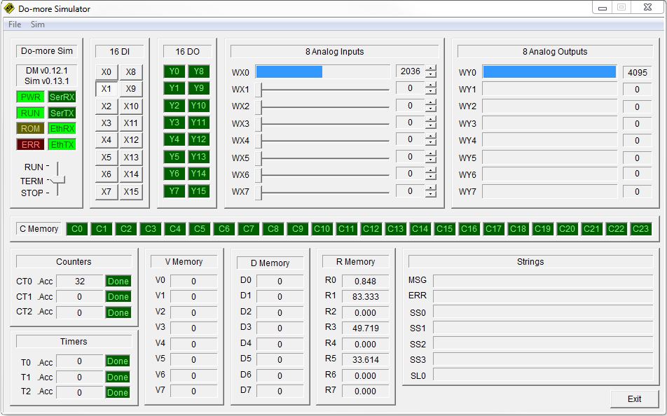
LEDs and Mode Switch
The LEDs and the Mode switch mimic operation of the front panel LEDs and the Mode Switch of a Do-more CPU.
Input Section
The Input section provides a way for the programmer to change the values of the discrete and analog input modules. The ability to write to these input locations can be enabled and disabled though the Sim-> Enable Inputs menu selection.
16 Discrete Inputs - there are 16 discrete inputs mapped into X0 - X15. Click a button once to turn that input ON (the button stays depressed), click it again to turn the input OFF.
8 Analog Inputs - there are 8 analog inputs mapped into WX0 - WX7. Click and drag the slider from left to right, or click the up and down arrows at the right edge to generate an input value of 0 to 4095. The current value will be displayed as a bar graph that fills from the left and will be displayed in numeric form beside the up/down arrows.
Output Section
The output section displays the current status of the simulator's discrete and analog outputs.
16 Discrete Outputs - there are 16 discrete outputs mapped into Y0 - Y15. If that output is ON the LED will be bright green, if it is OFF the output will be dark green.
8 Analog Outputs - there are 8 analog inputs mapped into WY0 - WY7. The current value ( 0 to 4095) will be displayed as a bar graph that fills from the left and will be displayed in numeric form at the right edge.
Memory Section
Because of space limitations the memory section cannot display the full complement of memory locations in the Simulator, only the current status of the following bit, numeric, and string elements in the simulator are displayed:
C Memory - the first 16 control relays (C0 - C23). If that output is ON the LED will be bright green, if it is OFF the output will be dark green
Counters - the current count (.Acc) and the Done bit of the first 3 Counters (CT0 - CT2)
Timers - the current time (.Acc) and the Done bit of the first 3 Timers (T0 - T2)
V Memory - he first 8 locations in the V Memory block (V0 - V7)
D Memory - the first 8 locations in the D Memory block (D0 - D7)
R Memory - the first 8 locations in the R Memory block (R0 - R7)
Strings - the system MSG and ERR strings, the first 4 Short Strings (SS0 - SS3), the first Long String (SL0)
Run Do-more Simulator
Clicking the Do-more/Sim button on the Online toolbar will open the
Launch and Connect to Do-more Simulator dialog according to the following:
-
If there is NOT a project currently open, Do-more Designer will launch the Simulator, then open a New Online project using the communication Link named MySim.
-
If there IS a project opened (either online or offline), Do-more Designer will launch the Simulator AND will launch a new instance of Do-more Designer and open a New Online project using the communication Link named MySim. The current instance of Do-more Designer and its project are left intact.
-
If there is an project currently using the MySim link and it is minimized or 'behind' other applications, Do-more Designer will bring the currently running instance of the Simulator to the front.
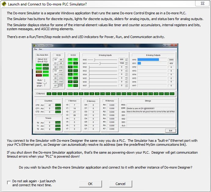
Do not ask again - just launch and connect next time - check this option to bypass this dialog the next time the Do-more Sim button on the toolbar is clicked.
Click OK to launch the Simulator.
Click Cancel to close the dialog without launching the Simulator.
Do-more PID Process Simulator
The Do-more Simulator includes a PID Process simulator that can be used to demonstrate the process control abilities of the CPU, or for testing potential changes to existing control solutions by working with the process control instructions in a simulation environment before deploying the control solution to a Do-more CPU. The PID process simulator uses a first order filter plus a dead time calculation to provide the simulated PID loop response.
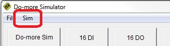
The PID Process Simulator is opened by clicking 'Sim' on the toolbar of the Simulator and selecting Setup PID Process Simulator.
The PID Process Simulator will use:
-
the Simulator's first input (WX0) to make the loop calculations for the Process Variable (PV)
-
the Simulator's second analog input (WX1) to provide a manually adjustable Set Point (SP) value.
-
the Simulator's first analog output (WY0) to make the value available to the rest of the program (Output)
Do-more Designer contains a built-in structure for the PID Process Simulator (called $IntProcSim) that contains the following fields used to control the simulation:
.DeadTime: - The amount of time (in seconds) before an output change begins to affect the PV. This is the dead time portion of the process simulation calculation. The range of values is 0 to 3600 seconds.
.TimeConstant: - The period (in seconds) after which 63% of the Output change has been applied to the PV. The range of values is 0 to 3600 seconds.
.Noise: - the PID process simulator can inject some random noise into the system. Change the value from 0 to a number between 0.0 and 1.0 to specify the amplitude of the random noise to be injected on the PV (0.0 is less noise than 1.0).
.Enable: - starts and stops the process simulation
This dialog will write values for these fields or they can be set by the ladder logic in the CPU.
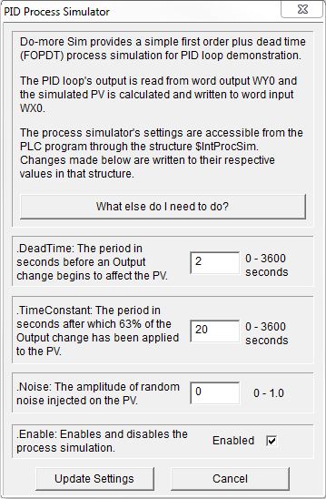
Update Settings - click this button to write the above three values to the Simulator.
Exit PID Simulator - click this button to close the PID Process Simulator.
The PID Process Simulator requires two ladder logic instructions in the Simulator before it can operate properly. These two instructions ( a PID and a SCALE ) will use the I/O in the simulator to provide space for the PID calculation and user input.
Click the What else do I need to do? button to display a dialog that details the instructions that must be added to the ladder program to make the PID process simulator work. An example project named PID1.Dmd is shipped with Do-more Designer that already contains the required ladder logic components that are described below.
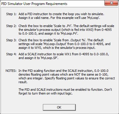
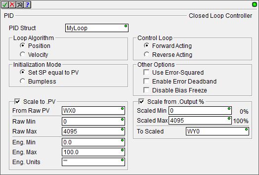
Add a Closed Loop Controller (PID) instruction with the following parameters:
give it the name MyLoop
set Position, Forward Acting, Set SP equal to PV, and do NOT select any other options
check the 'Scale to .PV' box to use WX0 as the Process Variable
make sure it's raw scaled range is 0 to 4095, and it's Eng scaled range is 0.0 to 100.0
Make sure to use floating point representations of the 0.0 and 100.0 numbers (not 0 and 100) in the SCALE portions of the instruction.
check the 'Scale from .Output %' box to use WY0 as .Output
make sure it's scaled range is 0 to 4095 and To Scaled is set to WY0
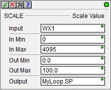
Next, add a Scale Value (SCALE) instruction to use WX1 as a user-controllable Set Point (SP).
set the Input to WX1
make sure the In range is 0 to 4095
make sure the Out range is 0.0 to 100.0
Make sure to use floating point representations of the 0.0 and 100.0 numbers (not 0 and 100) in the SCALE instruction.
make sure the output is set to MyLoop.SP
Select Comm Port
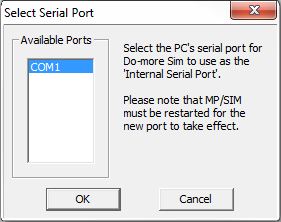
The Do-more Simulator can use one of the computer's onboard serial ports as the Internal Serial Port (@IntSerial). The Sim-> Select Comm Port menu selection will open this dialog which will list the available serial ports on the computer. Highlight the serial port in the list to use and click OK.
Note: If the port selection is changed the Simulator must be restarted for the change to take effect.