Topic: DMD0282

Memory Image Manager
A project's Memory Image is used to store data values from memory locations in the PLC as part of the offline project.The contents of the Memory Image can then be downloaded to the PLC as needed, or optionally any time Do-more Designer project is downloaded to the PLC. A new Do-more Designer project DOES NOT contain a Memory Image, you must create and maintain both the Memory Image configuration and the Memory Image data manually.
The Memory Image only stores data values for memory locations that are marked as Retentive![]() Memory marked as retentive will hold its state through a power cycle or a Program-to-Run mode transition. The status of memory NOT marked as retentive will be cleared at power up and during a Program-to-Run mode transition. in the Memory
Configuration, so before creating a Memory Image make sure the retentive memory in the PLC is setup the way you want it through the Memory
Configuration section of the System Configuration.
Memory marked as retentive will hold its state through a power cycle or a Program-to-Run mode transition. The status of memory NOT marked as retentive will be cleared at power up and during a Program-to-Run mode transition. in the Memory
Configuration, so before creating a Memory Image make sure the retentive memory in the PLC is setup the way you want it through the Memory
Configuration section of the System Configuration.
The Memory Image file can upload the initial data for each of the selected retentive memory ranges from the connected PLC, or all of the data can be initially cleared. Once the Memory Image is created and it's contents are initially set, the contents of the Memory Image file can be updated by the following operations:
One of the Refresh from PLC selections is used to get new data from the connected PLC
One of the Refresh from Disk selections is used to get new data from the offline copy of the project.
When the Modify Region Data operation is used to manually edit the data.
When connecting to the PLC, the PLC copy of the Memory Image configuration will be compared to the offline version and any differences will be noted on the Resolve Online/Offline Differences dialog, and must be resolved like differences in the other sections of the project.
The Memory Image Manager can also be used during of the Generate DMLoader Image creation process to include the contents of the Memory Image in the DMLoader image file.
To open the Memory Image Manager, select Tools -> Memory Image Manager from the Menu bar or click the Memory Mgr button on the Tools toolbar.
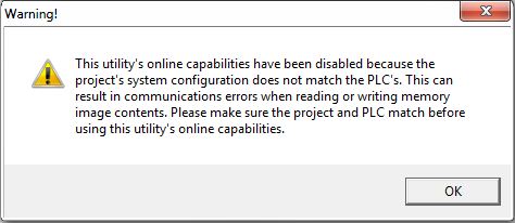
Note: If the Memory Configuration in the connected PLC does not match the Memory Configuration in the project you will see the following message box telling you that you should synchronize the Memory Configurations before you continue:
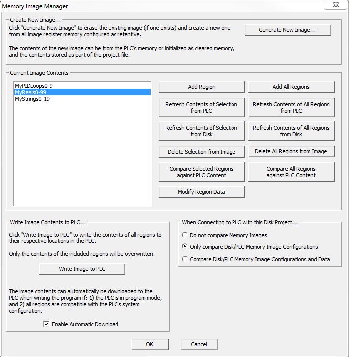
Create New Image...
Clicking the Generate New Image will open the following dialog:

This dialog will create a Memory Image file within your project (if a Memory Image exists it's contents will be erased ) and add all of the memory blocks that are marked as retentive to the Memory Image. The initial contents of the Memory for each region of the retentive ranges will be set from one of the following:
Create New Memory Regions with Current PLC Data - read the current values for each element in each region from the currently connected PLC.
Create New Memory Regions Zeroed / Cleared Data - for each memory block marked as retentive, if that memory region consists of numeric locations, they will all be initialized to 0. If that memory region consists of Strings, all of the Strings will be cleared.
Cancel will exit without creating a new Memory Image file (if none exists), or without erasing the current Memory Image for the open project (if one already exists).
Current Image Contents
The Current Image Contents lists the regions of the controller's retentive memory that are currently included in the Memory Image. This section has functions to modify the contents of an existing Memory Image file, by adding new memory regions, refreshing the contents of the current memory regions, deleting one or more of the memory region, and editing the contents of the existing memory regions.
Add Region
Clicking the Add Region button will open a dialog that will list all of the retentive regions that are NOT ALREADY in the Current Image Contents list.
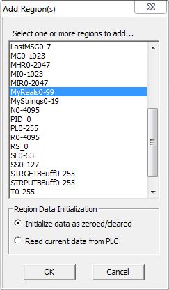
Select one or more of the retentive memory regions to add to the Memory Image file by clicking on one of the regions in the list; Click on any of the listed regions in the list to select multiple regions.
Region Data Initialization selects the initial contents of the region data from the following:
- Initialize Data as Zeroed / Cleared : if the Region consists of numeric locations, they will all be initialized to 0. If the memory region consists of Strings, all of the Strings will be cleared.
- Read Current Data from PLC will read the data for each location in the memory region from the currently connected PLC.
Click OK to add the highlighted regions to the Current Image Contents list.
Click Cancel to close the dialog without adding any regions to the Current Image Contents list.
Add All Regions
Clicking the Add All Regions button will add all of the retentive regions that are NOT already in the Current Image Contents list. If there are new memory regions being added to an existing list, the following dialog will be displayed asking how to initialize the data in each of the new regions:
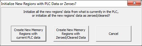
Create New Memory Regions with Current PLC Data will read the current values for each element in each new memory region from the currently connected PLC.
Create New Memory Regions Zeroed / Cleared Data : if the new memory region consists of numeric locations, they will all be initialized to 0. If the new memory region consists of Strings, all of the Strings will be cleared.
Cancel will exit without creating any new memory regions.
Refreshing Memory Image Contents
As stated earlier, the contents of a Memory Image are not automatically updated, they are only updated when one of the Refresh selections is used, when the Edit Region Data is used, or when a new Memory Image is generated.
Refresh Contents of Selection from PLC will reread the contents of the currently highlighted regions from the PLC and store the newly read values in the Memory Image. Click on any entry to select multiple regions in the list.
Refresh Contents of All Regions from PLC will reread the contents of the all the regions in the Current Image Contents list from the PLC and store the newly read values in the Memory Image file.
Refresh Contents of Selection from Disk will reread the contents of the currently highlighted regions from the offline copy of the Memory Image. Click on any entry to select multiple regions in the list.
Refresh Contents of All Regions from Disk will reread the contents of the all the regions in the Current Image Contents list from the offline copy of the Memory Image.
Deleting Regions from the Memory Image
Delete Selection from Image will remove the currently highlighted regions from the Current Image Contents list. Click on any entry to select multiple regions in the list.
Delete All Regions from Image will remove all of the regions from the Current Image Contents list.
Compare Regions Contents
If the Memory Image configurations match you can use the two following options to compare the region data in the Memory to the region data in the PLC:
Compare Selected Regions Contents against PLC Content will compare the contents of the currently highlighted memory regions in the Memory Image to the contents of the same regions in the currently connected PLC. Click on any entry to select multiple regions in the list.
Compare All Regions Contents against PLC Content will compare the contents of all of the memory regions in the Memory Image file to the contents of the same regions in the currently connected PLC.
Modify Region Data
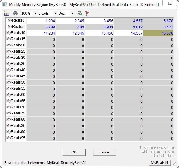
Click the Modify Region Data button to open a dialog where the elements or structure fields in the selected region can be set to constant values. If the highlighted region is a block of simple types, a dialog similar to the following will open.
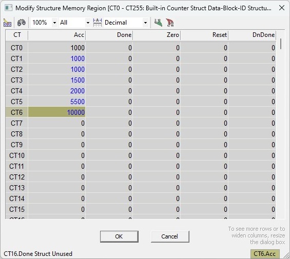
The Modify Region Data dialog uses color-coded display of the values to indicate various information about the values of the individual Elements in the region. A cell's background color of Olive Green indicates the current position of the edit cursor; Red indicates the text in that cell IS NOT VALID for the current data format, White means the Element IS USED in the current project, and Gray means the Element IS NOT USED in the current project.
Toolbar Buttons
If the highlighted region is a block of simple types, the Toolbar will have the following options:
Clear All Data in View will clear all of the values in dialog. If the values are bit or numeric they will be set to 0. If the values are Strings they will be cleared.
Note: this operation only clears the values in the dialog; it DOES NOT write the cleared values to the Memory Image to the disk or to the PLC.
Goto will locate the specified memory location in the dialog and move the edit cursor to that cell.
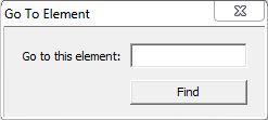
Go To This Element : enter the element to search for the click the Find button to perform the search. If the search is successful the view will move the edit cursor to the cell that contains the Element. If the search is unsuccessful it's mostly likely because the Element type is wrong or the Element is out of range.
Zoom Level sets the size of the data values displayed in the cells of the dialog. To change the Zoom Level, select one of predefined options in the drop-down list (500%, 300%, 200%, 150%, 100%, 90%, 75%) or type in a percentage value between 50 and 500.
Number of Columns sets the number of columns of Elements in the dialog. When the dialog is initially opened it will have 5 columns for data blocks that are numbered in decimal, and 4 columns for data blocks that are numbered in octal. To change the number of columns, select one of the predefined options in the drop-down list (1, 2, 5, 10, 15, 20, 25, 30), or enter any value from 1 to 32.
Display Format selects the data format of the values that will be displayed for all of the Elements in the dialog.
For Bit Elements the format selection is only decimal (0 or 1).
For Numeric Elements the format selections are Decimal, Hexadecimal (0x...), Octal (0...), and Binary (xxxx_xxxx_xxxx_xxxx).
For Real Elements the selections are Real (1.234) and Exponential (1.234E+000).
For String Elements the selections are ASCII (my text) and Quoted ("my text"). Use ASCII if the text contains only displayable characters; use Quoted if the text contains any non-displayable characters, for example <CR><LF>, or $N, or 0x0D0A.
Import Data will read in values from an external CSV (comma separated variables) file that has been previously exported from a Memory View, or exported from the Memory Image Manager, or exported by the Export Memory Data utility, or one that has been manually created with the appropriate format.
Only data from the import file that is from the same range of the same memory block that this dialog is using will be imported. Any time there is a mismatch between the range in the dialog and the range in the import file a message box will be displayed with details about exactly how much data was imported.
Refer to the Import Memory Data utility for details on the required format.
Export Data will store the current value for every Element in the dialog in an external file in CSV (comma separated variables) format. The exported file will be formatted the same way as the export file from the Export Memory Data utility.
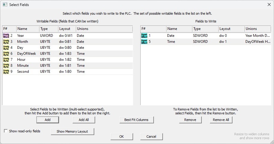
If the highlighted region contains structures, a dialog will open that contains a row for each structure in the block and a column for each structure field.
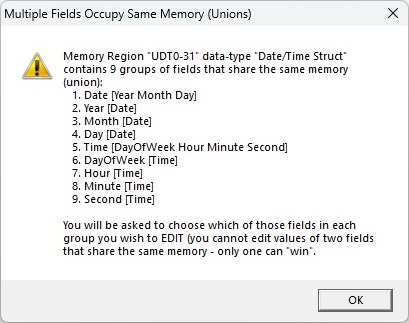
Note: if the selected structure contains unions (two or more fields that have been purposely mapped to the same memory location in the structure) you will see the following message then be required to select which of the fields of the union(s) will be modified in this dialog:
The Modify Region Data dialog uses color-coded display of the values to indicate various information about the values of the individual Elements in the region. A cell's background color of Olive Green indicates the current position of the edit cursor; Red indicates the text in that cell IS NOT VALID for the current data format, White means the Element IS USED in the current project, and Gray means the Element IS NOT USED in the current project.
Toolbar Buttons
If the highlighted region is a block of structures, the Toolbar will have the following options:
Clear All Data in View will clear all of the values in dialog. If the values are bit or numeric they will be set to 0. If the values are Strings they will be cleared.
Note: this operation only clears the values in the dialog; it DOES NOT write the cleared values to the Memory Image to the disk or to the PLC.
Goto will locate the specified memory location in the dialog and move the edit cursor to that cell.
Go To This Element : enter the element to search for the click the Find button to perform the search. If the search is successful the view will move the edit cursor to the cell that contains the Element. If the search is unsuccessful it's mostly likely because the Element type is wrong or the Element is out of range.
Zoom Level sets the size of the data values displayed in the cells of the dialog. To change the Zoom Level, select one of predefined options in the drop-down list (500%, 300%, 200%, 150%, 100%, 90%, 75%) or type in a percentage value between 50 and 500.
Which Fields to Display sets which collection of structure fields to display:
All displays all of the fields in the structure - even fields marked as read-only.
Critical will display only the fields marked as critical when the structure was created.
Useful will display only the fields marked as useful when the structure was created.
Auto-Fit Columns if possible, will adjust the widths of each fields displayed so that none of the field names are cropped, else it will evenly distribute the column widths within the overall width of the dialog.
Display Format selects the data format of the values in the currently highlighted column. The format selections are Decimal, Hexadecimal, Octal, Binary, Timer, IP Address, Month, Day of Week, Seconds (d/h/m/s), 1970 Epoch, Time, Date, ASCII, or Swapped ASCII.
Import Data will read in values from an external CSV (comma separated variables) file that has been previously exported from a Memory View, or exported from the Memory Image Manager, or exported by the Export Memory Data utility, or one that has been manually created with the appropriate format. Refer to the Import Memory Data utility for details on the required format.
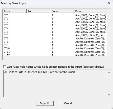
Enable the Zero / Clear Fields values whose fields are not included in the import (see report below) option to clear the values of fields in the structure that do not have a value specified in the import file.
Export Data will store the current value for every field of every structure in the dialog in an external file in CSV (comma separated variables) format. The exported file will be formatted the same way as the export file from the Export Memory Data utility.
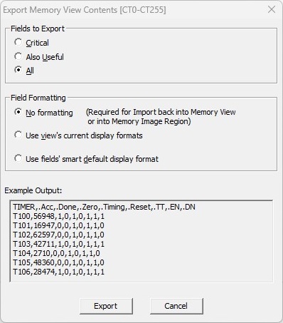
Fields to Export selects which collection of structure fields to export:
All selects all of the fields in the structure - even fields marked as read-only.
Critical selects only the fields marked as critical when the structure was created.
Useful selects only the fields marked as useful when the structure was created.
Field Formatting selects how each field's data will be stored in the export file.
No Formatting will export the values as displayed in the dialog. This is the proper selection if you intend to import data from this file at a later date.
Use View's Current Display Formats will export the field's values using any formatting selections made in this dialog.
Use Field's Smart Display Format will export the data using the field's format in the structure definition.
The Example Output window will show a sample of what the format selection will look like using the selections made.
Keystrokes and Mouse Actions
The keystrokes and mouse actions within the dialog are optimized for quick data entry of constant values into memory locations.
Navigating Within the Dialog
LEFT, RIGHT, UP, and DOWN arrow keys move the cursor one cell in the direction of that arrow.
TAB will move the cursor one cell to the right. If the cursor is on the last column of the view the cursor will move to the first column of the next row.
SHIFT+TAB will move the cursor one cell to the left. if the cursor is on the first column of the view the cursor will move to the last column of the previous row.
HOME will move the cursor to the first column in the same row in the view.
END will move the cursor to the last column in the same row in the view.
Multiple ways to Start an Edit Session for a Cell
Double click with mouse on a cell.
or Use the keyboard to begin entering a new value.
or SPACE will begin an edit session with the entire value in a cell selected.
Editing the Value in a Cell
UP arrow will increment the current value in the cell by one .
DOWN arrow will decrement the current value in the cell by one .
LEFT and RIGHT arrows will move the caret one digit to the left and right respectively within the current value.
DELETE will delete one digit to the right of the caret.
BACKSPACE will delete one digit to the left of the caret.
Using a Click & Drag with the mouse, or SHFT+Right Arrow or SHFT+Left Arrow will select the individual characters of the value in a cell.
Double-Click will select all of the contents of the cell.
CTRL+C will copy the selection to the clipboard.
CTRL+X will cut the selection from the cell and place the selection in the clipboard.
CTRL+V will paste the clipboard contents into the cell at the current cursor location.
Ending the Edit Session
TAB will accept the current value in the cell, move the cursor to the cell in the next column to the right and begin editing the value in that cell
SHIFT+TAB will accept the current value in the cell, move the cursor to the cell in the previous column to the left and begin editing the value in that cell
ENTER will accept the current value in the cell and leave the cursor on that cell.
A mouse click in another cell will accept the current value in the cell being edited, then move the cursor to the cell that was clicked on.
ESCAPE will abort the edit session and leave the original value of that cell intact.
Write Image Contents to PLC...
Click the Write Image to PLC to copy the contents of the current Memory Image to the their respective locations in the controller, overwriting whatever values are in the destination locations.
Enable Automatic Download - enabling this option will download the current contents of the Memory Image each time Do-more Designer downloads the project to the controller if the following conditions are met:
The controller is in STOP (Program) mode: the Memory Image contents WILL NOT be downloaded if the controller is in RUN mode.
All of the regions in the Memory Image file are compatible with the current memory configuration in the PLC.
On Connection Options
When you have a project that contains a Memory Image, the following three options specify what action to take when you connect to a PLC that also has a Memory Image:
- Do Not Compare Memory Images - neither the Memory Image configuration nor the contents of the memory regions will be compared.
- Only Compare the Disk/PLC Memory Image Configurations - only compare the Memory Image configuration of the offline project to the Memory Image configuration in the PLC, do NOT compare the contents of the regions.
- Compare Disk/PLC Memory Image Configurations and Data - compare the Memory Image configuration of the offline project to the Memory Image configuration in the PLC AND compare the values in the regions.
If the comparison operation fails, you will see the Resolve Online / Offline differences dialog. This is the same dialog you see when the System Configuration, or the Code Blocks or the Documentation don't match.
See Also:
Resolve Online/Offline Differences
Related Topics: