Topic: DMD0203

Using the Configure Link Dialog to Modify an Existing Communication Link
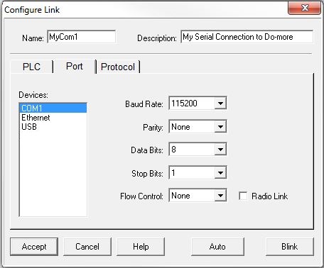
Clicking the Edit... button in the Links section of the Launchpad opens the Configure Link dialog. This utility allows the programmer to manually create a new link by entering all of the required communication information, or allow the programmer to change the configuration of an existing communication link.

The Name is a 16-character name that must be unique on the PC running the programming software.
The Description is a 32 character text string that describes this communication link.
Clicking the Accept button will cause Do-more Designer to attempt to communicate with the PLC using the current communication parameters in an attempt to verify that the selections made on the PLC, Port, and Protocol tabs are correct.
If the link test is successful, the dialog
will save these current settings in the Link, the link will be marked
as Enabled, then the Configure Link dialog will close. If
the link test in unsuccessful the programmer will be presented with the
following options:
-
Return will go back to the Configure Link dialog and correct the Port tab entries
-
Continue will not change the Port settings to match the CPU that was found during the link test, these settings will be saved in the Link, the link will be marked as Disabled, then the Configure Link dialog will close. B be aware the communication link with settings in this state will not work.
-
Auto will instruct Do-more Designer to attempt to communicate with the PLC using the currently defined set of communication parameters. If the test is unsuccessful, Do-more Designer will sequence through the combinations of communication parameters in an attempt to find a set of parameters that will work. If this is successful the PLC and Port tab entries will be changed to match the CPU that was found during the link test.
-
Retry will cause Do-more Designer to retry the attempt to communicate with the target CPU.
Clicking the Cancel button will exit the Configure Link dialog.
Clicking the Help button will display the Help topic for this dialog.
Clicking the Auto button will instruct Do-more Designer to attempt to communicate with the PLC using the currently defined set of communication parameters. If the test is unsuccessful, Do-more Designer will sequence through the combinations of communication parameters in an attempt to find a set of parameters that will work. If this is successful the PLC and Port tab entries will be changed to match the controller that was found during the link test.
If a successful link has been created, clicking the Blink will cause the ERR led on the Do-more CPU specified in the link to blink for 15 seconds, this can be used to verify that the selected entry is accessing the correct PLC.
The PLC Tab:
The PLC tab of the Configure Link dialog selects the target CPU for the communication link.
The PLC Family contains the list of PLC Families:
-
Do-more BRX Series select this option if the target CPU is in the BX-DM1x Series.
- Do-more H2 Series select this option if the target CPU is in the H2-DM1x Series.
-
Do-more Simulator select this option if the target CPU is the Do-more Simulator running on a PC.
- Do-more T1H Series select this option if the target CPU is in the Terminator Series
-
Unspecified select this option if the target CPU is unknown. Using the Auto-baud process described above can determine the correct PLC Family.
The PLC Type group designates which device from the selected PLC Family is the target:
-
if the selected Family is the Do-more BRX Series - the following options exist:
-
BX-DM1E-x - BRX series CPU with Serial, USB and Ethernet ports.
-
if the selected Family is the Do-more H2 Series - the following options exist:
-
H2-DM1 - DL205 series CPU with Serial and USB ports.
-
if the selected Family is the Do-more Simulator - the only available option is:
-
if the selected Family is the Do-more T1H Series - the following options exist:
-
T1H-DM1 - Terminator series CPU with Serial and USB ports.
-
T1H-DM1E - Terminator series CPU with Serial, USB and Ethernet ports.
-
if the selected Family is the Unspecified - the only option is:
-
Unspecified - select this option if the target CPU is unknown. Using the Auto-baud process described above can determine the correct PLC Type.
The Port Tab:
The Port tab of the Configure Link dialog selects the PC port to use in the communication link and the communication parameters required for that port.
Selecting one of the port options from the Devices group will display the appropriate communications parameter entry fields for that Device as follows:
The Link is Using a Serial Port
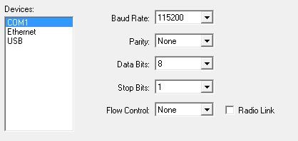
If a serial COM
port is selected in the Devices group the following fields are displayed:
-
Data Bits selects the desired number of data bits from the list.
-
Stop Bits selects the desired number of stop bits from the list.
-
Flow Control selects the desired flow control option from the list.
-
Enable the Radio Link option to assert the DTR line for the CR-HN series radio modems that are sold by Automationdirect.com.
The Link is using an Ethernet Port

If an Ethernet port is selected in the Devices group the following fields are displayed:
Transport Protocol selects the desired Ethernet protocol. UDP/IP (TCP/IP) is the only Ethernet protocol supported by the on-board port of a Do-more CPU. IPX protocol is only supported when creating a link through an ECOM100 module. IPX protocol is ONLY available on the Windows XP operating system.
The Node
Address group designates which of the following options to reference
the communication link by:
-
Module ID is the user assigned node number, this number is set via the DIP switch or NetEdit.
-
Name is the user assigned 16 character name.
-
IP Address (the default for IP) is the user assigned TCP/IP address of the Do-more CPU or the ECOM100 module.
-
Ethernet Address (the default for IPX) is the factory assigned MAC address of the Do-more CPUor the ECOM100 module.
Click the Advanced Settings button to invoke the Ethernet Advanced Settings dialog to change the following:

Timeout is the amount of time (in milliseconds) the Comm Server will wait for an "ACK" response from the CPU.
Application Timeout is the amount of time (in milliseconds) the Comm Server will wait for the "DATA" response from the CPU.
Scan Delay specifies the "poll rate" (in milliseconds) of the link. This lets the Comm Server pace the comm requests going to the CPU if needed.
Retries specifies the number of times a comm transaction will be retried before it is reported as an error.
UDP Port Number specifies the port number the Comm Server will use to create the connection. The default value is 28784 (0x7070).
Click the Set Default button to return these four fields to their default values.
Click the Module Setup button to open NetEdit, which is the utility that allows the programmer to initially assign, or to change the Module ID, Name, Description, and IP Address of a Do-more CPU or an ECOM100 module.
The Link is using a USB Port

USB ports that are already in use by another link or by another process outside of Do-more will not be displayed in this list.
If a USB port is selected in the Devices group the following fields are displayed:
Unit Serial
Number is the 12 digit serial number of the Do-more controller.
Click the Use Selected
button to enter the 12 digit number of the currently highlighted
entry in the Connected Units list
Connected
Units displays a list of the Do-more CPUs that are currently
connected via a USB port.
Click the Refresh List button to have Do-more Designer poll the USB ports on the PC for Do-more CPUs. It is possible to use the same USB port to create links to multiple Do-more CPUs, just make sure the USB port is not in use when the Refresh List operation is being executed.
The Protocol Tab:
The Protocol tab of the Configure Link dialog selects the communication protocol to use when communicating with the Do-more controller.

The only Protocols option for use within Do-more Designer is the Do-more protocol.
Address is the Module ID of the CPU
The Advanced Settings group designate protocol timing options:
Timeout is the time (in milliseconds) to allow the protocol to wait on a response from a CPU.
Retries is the number of time to retry sending a request to a controller before reporting a communication error.
See Also:
Using the Link Wizard to Create New Communication Links
Using Configure Link to Modify Existing Communication Links
Using Link Info to Monitor Communication Links
Related Topics: