Topic: DMD0550
![]()
CTRIO Module Configuration - Configure IO
Configure IO Overview:
To get to the CTRIO Module Configuration - Configure IO dialog:
-
Follow this menu path: PLC --> System Configuration --> Module Configuration(s). This pulls up the System Configuration dialog.
-
Double-click on the CTRIO to configure. This pulls up the Edit CTRIO/CTRIO2 Configuration dialog.
-
Press the <Configure I/O> button.
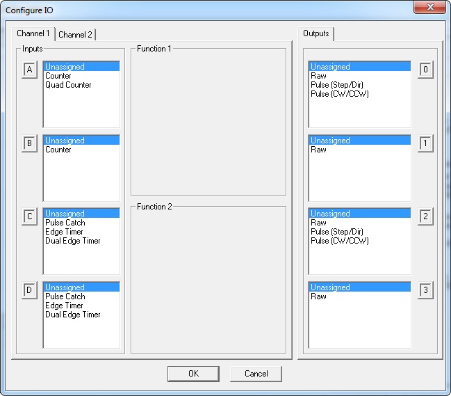
Here is where the input and output functions of the CTRIO are defined.
-
Channel 1 / Channel 2 - These tabs allow the configuration of all 4 of each Channel's inputs (A, B, C, D) and correspond directly with the CTRIO's input terminals (1A-1D & 2A-2D). The current options for a given input are displayed in the window, however, these options change dynamically as different options are chosen.
-
Function 1 / Function 2 - These boxes change showing further options for the input functions chosen.
-
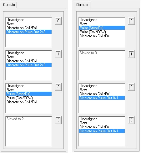
Outputs - This allows the configuration of all 4 of the outputs (0, 1, 2, 3) and correspond directly with the CTRIO's output terminals (Y0-Y3). The current options for a given output are displayed in the window, however, these options change dynamically as different options are chosen.
Configuring CTRIO Inputs
There are basically 10 input settings but they are not supported on all inputs and some are mutually exclusive of others. However the configuration dialog will change dynamically to show which ones are available:
-
Counter - Counts single-ended pulses. Click here for details.
-
Quad Counter - Counts quadrature encoder pulses. Click here for details.
-
Pulse Catch - Qualifies a short-duration pulse and lengthens its duration. Click here for details.
-
Edge Timer - Measures the time from edge to edge of a pulse. Click here for details.
-
Dual Edge Timer - Measures the time from the edge of a pulse on one input to the edge of a pulse on a second input. Click here for details.
-
Reset Fn1 / Reset Fn2 - Allows input to reset the count value on Function 1 or Function 2 counters. Click here for details.
-
Capture Fn1 - Allows input to snapshot the count on Function 1 and store it into the second input register. Click here for details.
-
Inhibit Fn1 - Allows input to inhibit Function 1 counter from counting pulses. Click here for details.
-
Limit Out 0 / Limit Out 2 - Allows the input to be used in conjunction with a CTRIO pulse output function. Click here for details.
Configuring CTRIO Outputs
There are basically 5 output settings but they are not supported on all outputs and some are mutually exclusive of others. However the configuration dialog will change dynamically to show which ones are available:
-
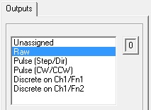
Unassigned - The output has no function.
-
Raw - Allows the Do-more controller to directly turn this output ON/OFF. Click here for details.
-
Discrete on Ch1/Fn1 / Discrete on Ch1/Fn2 / Discrete on Ch2/Fn1 / Discrete on Ch2/Fn2 - Allows the output to be used in conjunction with a CTRIO input function. Click here for details.
-
Discrete on Pulse Out 0/1 / Discrete on Pulse Out 2/3 - Allows the output to be used in conjunction with a CTRIO pulse output function. Click here for details.
-
Pulse (Step/Dir) / Pulse (CW/CCW) - Uses two outputs (0 & 1 or 2 & 3) where the first one is a pulse output and the second one is a direction output bit (step/dir) or where the first one generates pulses for clockwise motion and the second one generates pulses for counter-clockwise motion (cw/ccw). Click here for details.
CTRIO Input Functions:
Counter Function
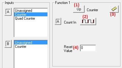
This function is available for Ch1A, Ch1B, Ch2A & Ch2B inputs. It counts single-ended pulses. By default there are 4 basic options available:
-
(1) Up / Down (button) - Pressing this button changes whether the counter counts up or down.
-
(2) Edge (button) - Pressing this button changes whether the rising edge or falling edge is counted.
-
(3) Scaling (button) - Pressing this button allows the count value to be scaled and calls up the Scaling Wizard. Click here for help with scaling.
-
(4) Reset Value - Clicking in the data input field allows a count reset value to be entered. This is the value that will be loaded into the counter when a reset (hardware or software) occurs. It must be a value between -2,147,483,648 and +2,147,483,647.
The raw count value (if there is no scaling) is reported in the CTRIO structure. For example:
-
$CTRIO_000_C1F1.iReg1 - Channel 1 function 1, signed integer register 1
Other interfaces to the count function in the CTRIO structure are, for example:
Also a software reset bit can be set to reset the count to the reset value, for example:
-
$CTRIO_000_C1F1.Reset - Channel 1 function 1, bit can be manually set ON to reset the current count to reset value
The counter function can be further modified by the C & D inputs and will be covered in detail below. These are the already-mentioned Reset Fn1 / Reset Fn2, Capture Fn1 and Inhibit Fn1 input functions.
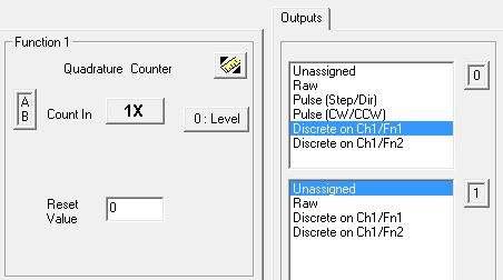
Quad Counter
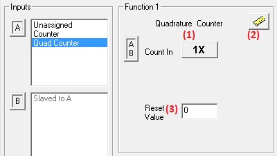
This function is available for Ch1A/Ch1B & Ch2A/Ch2B input pairs. It counts quadrature encoder pulses. By default there are 3 basic options available:
-
(1) Multiplier (button) - Pressing this button cycles through 1X, 2X or 4X choices.
-
1X - counts leading edge of pulse on input A.
-
2X - counts leading and falling edges of pulse on input A.
-
4X - counts leading and falling edges of pulses on both input A & input B.
-
(2) Scaling (button) - Pressing this button allows the count value to be scaled and calls up the Scaling Wizard. Click here for help with scaling.
-
(3)Reset Value - Clicking in the data input field allows a count reset value to be entered. This is the value that will be loaded into the counter when a reset (hardware or software) occurs. It must be a value between -2,147,483,648 and +2,147,483,647.
The raw count value (if there is no scaling) is reported in the CTRIO structure. For example:
-
$CTRIO_000_C1F1.iReg1 - Channel 1 function 1, signed integer register 1
Other interfaces to the count function in the CTRIO structure are, for example:
-
$CTRIO_000_C1F1.AtResetValue - Channel 1 function 1, bit is ON if count is equal to the reset value
Also a software reset bit can be set to reset the count to the reset value, for example:
-
$CTRIO_000_C1F1.Reset - Channel 1 function 1, bit can be manually set ON to reset the current count to reset value
The quad counter function can further be modified by the C & D inputs which will be covered in detail below. These are the already-mentioned Reset Fn1, Capture Fn1 and Inhibit Fn1 input functions.
Pulse Catch
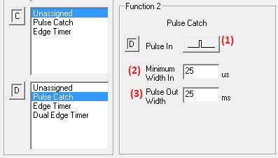
This function is available for Ch1C, Ch1D, Ch2C & Ch2D inputs. This function qualifies a short-duration pulse by a minimum width in microseconds and outputs a software bit of millisecond length. This allows the Do-more controller to catch unusually quick pulses that normal input modules would miss. By default there are 3 basic options available:
-
(1) Pulse Edge (button) - Pressing this button changes whether the input looks for a rising or falling edge pulse.
-
(2) Minimum Width In - This is the minimum pulse width in microseconds you want to capture. Transients shorter than this duration will be ignored. This value must be between 1 and 2,147,483,647 microseconds.
-
(3) Pulse Out Width - This is the duration in milliseconds you want the CTRIO to send in response to the input pulse. This value must be between 1 and 2,147,483,647 milliseconds.
To enable the function once it is configured, a bit in the CTRIO structure must manually be set ON. For example:
Once the function is enabled, then when a pulse has been detected, this is reported in the CTRIO structure. For example:
-
$CTRIO_000_C1F1.CapturedStart - Channel 1 function 1, capture started bit
When the pulse is qualified then a bit in the CTRIO structure is set for the Pulse Out Width duration. For example:
-
$CTRIO_000_C1F1.Output - Channel 1 function 1, pulse catch output bit
Note: It is also possible to tie the output of this function to one of the CTRIO outputs by choosing that output's Discrete on Chx/Fnx option.
Edge Timer
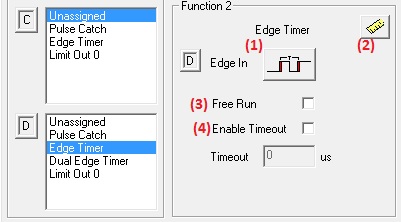
This function is available for Ch1C, Ch1D, Ch2C & Ch2D inputs. This function measures the time from edge to edge of a pulse. By default there are 4 basic options available:
-
(1) Edges Definition (button) - Pressing this button cycles through 4 choices of how the time will be measured:
-
Rising edge to rising edge
-
Rising edge to falling edge
-
Falling edge to rising edge
-
Falling edge to falling edge
-
(2) Scaling (button) - Pressing this button allows the count value to be scaled and calls up the Scaling Wizard. Click here for help with scaling.
-
(3) Free Run - Checking this box causes the edge timer to continuously arm itself after each measurement resulting in a continuous (moving average) measurement. If unchecked, the edge timer must be manually armed for each measurement.
-
(4) Timeout - Checking this box allows a value to be entered in the Timeout data field. The purpose of this option is when the first edge is detected, if it takes too long (the Timeout value) for the second edge to occur, then a timeout bit is set. This keeps the edge timer from getting "stuck" just waiting for that second edge. The Timeout value must be between 1 and 2,147,483,647 microseconds.
To enable the function once it is configured, a bit in the CTRIO structure must manually be set ON. For example:
-
$CTRIO_000_C1F1.EnableCapture - Channel 1 function 1, enable edge timer bit
Once the function is enabled, then when a pulse has been detected, this is reported in the CTRIO structure. For example:
-
$CTRIO_000_C1F1.CapturedStart - Channel 1 function 1, first edge detected bit
When the first edge is detected the timer starts running and is reported in the CTRIO structure. For example:
-
$CTRIO_000_C1F1.iReg2 - Channel 1 function 2, signed integer running timer value in microseconds
If the second edge is detected a successful measurement and its value are reported in the CTRIO structure. For example:
-
$CTRIO_000_C1F1.CaptureComplete - Channel 1 function 1, second edge detected and measured bit
-
$CTRIO_000_C1F1.iReg1 - Channel 1 function 1, signed integer captured time value in microseconds
If Timeout is enabled and the second edge is not detected before the Timeout value is reached, this is reported in the CTRIO structure. For example:
-
$CTRIO_000_C1F1.Timeout - Channel 1 function 1, edge timer timeout bit (second edge not detected in time)
If free run is not enabled, then the edge timer must be re-enabled to measure another edge time. If free run is enabled the edge timer re-enables itself.
Dual Edge Timer
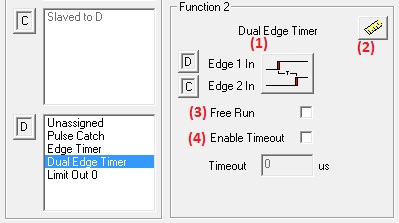
This function is available for Ch1C/Ch1D, Ch1D/Ch1C, Ch2C/Ch2D & Ch2D/Ch2C input pairs. This function measures the time from the edge of a pulse on one input to the edge of a pulse on a second input. By default there are 4 basic options available:
-
(1) Edges Definition (button) - Pressing this button cycles through 4 choices of how the time will be measured:
-
Rising edge of one input to rising edge on other input
-
Rising edge of one input to falling edge on other input
-
Falling edge of one input to rising edge on other input
-
Falling edge of one input to falling edge on other input
-
(2) Scaling (button) - Pressing this button allows the count value to be scaled and calls up the Scaling Wizard. Click here for help with scaling.
-
(3) Free Run - Checking this box causes the dual edge timer to continuously arm itself after each measurement resulting in a continuous (moving average) measurement. If unchecked, the dual edge timer must be manually armed after each measurement.
-
(4) Timeout - Checking this box allows a value to be entered in the Timeout data field. The purpose of this option is when the first edge is detected on the first input, if it takes too long (the Timeout value) for the second edge to occur on the second input, then a timeout bit is set. This keeps the dual edge timer from getting "stuck" just waiting for that second edge. The Timeout value must be between 1 and 2,147,483,647 microseconds.
To enable the function once it is configured, a bit in the CTRIO structure must manually be set ON. For example:
-
$CTRIO_000_C1F1.EnableCapture - Channel 1 function 1, enable dual edge timer bit
Once the function is enabled, then when a pulse has been detected on the first input, this is reported in the CTRIO structure. For example:
-
$CTRIO_000_C1F1.CapturedStart - Channel 1 function 1, first edge on first input detected bit
When the first edge is detected the timer starts running and is reported in the CTRIO structure. For example:
-
$CTRIO_000_C1F1.iReg2 - Channel 1 function 2, signed integer running timer value in microseconds
If the second edge is detected a successful measurement and its value are reported in the CTRIO structure. For example:
-
$CTRIO_000_C1F1.CaptureComplete - Channel 1 function 1, second edge detected and measured bit
-
$CTRIO_000_C1F1.iReg1 - Channel 1 function 1, signed integer captured time value in microseconds
If Timeout is enabled and the second edge is not detected before the Timeout value is reached, this is reported in the CTRIO structure. For example:
-
$CTRIO_000_C1F1.Timeout - Channel 1 function 1, dual edge timer timeout bit (second edge not detected in time)
If free run is not enabled, then the dual edge timer must be re-enabled to measure another dual edge time. If free run is enabled the dual edge timer re-enables itself.
Reset Count
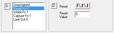
Reset Fn1 is available on Ch1C or Ch2C only if a counter or quad counter has been configured for function 1. In other words, only if Ch1A or Ch2A are configured as a counter, or Ch1A/Ch1B or Ch2A/Ch2B are configured as a quad counter. This function modifies the counter/quad counter function box by adding a button. It allows the C input to reset the count value to the reset value. By default there is one option:
-
Reset Edge (button) - Pressing this button configures the reset to execute either on the rising edge, falling edge, high level or low level of input C. The edge reset sets the current count to zero on the specified edge (rising or falling) of the reset pulse. The level reset resets the count to zero (as long as the reset pulse is held high (or low depending on configuration)). When the reset pulse is not at level anymore, the count resumes.
Reset Fn2 is available on Ch1D or Ch2D only if a counter has been configured for Ch1B or Ch2B respectively. It is functionally equivalent to Reset Fn1.
Note: It is also possible to reset the count using the CTRIO's own channel/function structure member bit (.Reset). When this bit is ON, the count is reset; when this bit is OFF, the counter function is free to count.
Capture Count
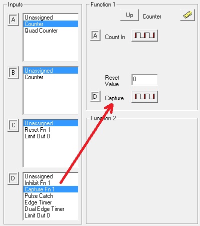
Capture Fn1 is available on Ch1D or Ch2D only if a counter or quad counter has been configured for function 1. In other words, only if Ch1A or Ch2A are configured as a counter, or Ch1A/Ch1B or Ch2A/Ch2B pairs are configured as a quad counter will the capture function be available. This function modifies the counter/quad counter function box by adding a button. It allows input D to snapshot the count on function 1 and store it into a CTRIO structure register. By default there is one option:
-
Capture Edge (button) - Pressing this button configures the capture to execute either on the rising edge or falling edge of input D.
This function works in the following manner:
-
The capture function must be enabled by turning ON the channel/function capture enable structure member (e.g. $CTRIO_000_C1F1.EnableCapture).
-
Once the capture is enabled, the CTRIO monitors the Capture Fn1 input.
-
When the capture signal is seen on the input, the channel/function count capture structure member is turned ON (e.g. $CTRIO_000_C1F1.CountCaptured)
-
Also, when the capture signal is seen the CTRIO "snapshots" the current count into the second CTRIO structure register (e.g. $CTRIO_000_C1F1.iReg2).
-
To repeat a capture, the capture enable bit (e.g. $CTRIO_000_C1F1.EnableCapture) must be turned OFF, then refer back to Step 1 above.
Inhibit Counting
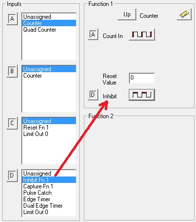
Inhibit Fn1 is available on Ch1D or Ch2D only if a counter or quad counter has been configured for function 1. In other words, only if Ch1A or Ch2A are configured as a counter, or Ch1A/Ch1B or Ch2A/Ch2B pairs are configured as a quad counter will the inhibit function be available. This function modifies the counter/quad counter function box by adding a button. It allows input D to inhibit function 1 counter from counting pulses. By default there is one option:
-
Inhibit Level (button) - Pressing this button configures the inhibit to execute either in the high state or low state of input D.
When the inhibit signal is seen on input D, it causes the CTRIO function 1 counter to stop counting pulses. When the inhibit signal disappears, counting will resume.
Limit For Output
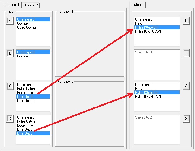
Limit Out 0 and Limit Out 2 are available on Ch1C, Ch1D, Ch2C & Ch2D only if Output0/1 and Output2/3 are configured as either pulse (step/direction) or pulse (cw/ccw). This function allows input C and/or input D to be used in conjunction with a CTRIO pulse output instruction. The CTRIO instructions that can utilize this feature are:
-
CTAXLIMT (CTRIO2 Axis Run Trapezoid w/Limits) - Because this instruction requires choosing a limit.
-
CTRUNPOS (CTRIO Run Position Mode) - If the profile being used in the instruction is:
-
CTRUNVEL (CTRIO Run Velocity Mode) - If a limit is chosen in the instruction.
CTRIO Output Functions:
Raw Output
Raw is available on Out0, Out1, Out2 & Out3. This function allows the Do-more controller to directly turn this output ON or OFF via a CTRIO structure. For example:
-
$CTRIO_000_Out0.Output - Output 0, raw output bit
Setting ON or resetting this bit OFF directly causes the CTRIO output to turn ON or go OFF.
Discrete Output For Input Function
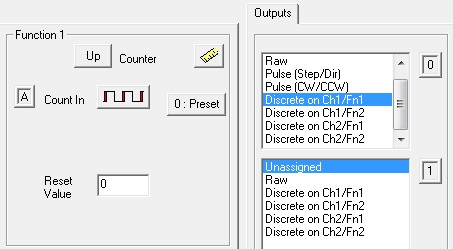
Discrete on Chx/Fnx is available on Out0, Out1, Out2 & Out3. This function allows the output to be used in conjunction with a CTRIO input function and preset or to be used by previously defined discrete output tables. This function modifies the function box by adding a preset button. By default there can be 2 options (Preset mode and Level mode):
-
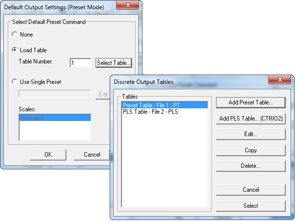
(1) Preset (button) - If no default preset mode action is needed for this output, then there is nothing else to do. If a default preset mode action is desired, then pressing this button will pull up the Default Output Settings (Preset Mode) dialog. By default this is set to None. Any other setting on this dialog will be executed when the CTRIO is taken from program to run mode, or powered up. Default preset mode actions are:
-
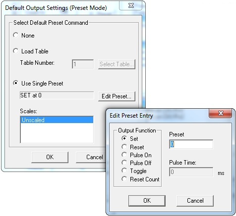
Use Single Preset - Instead of automatically loading a previously configured discrete output table, this allows the selection of a single preset, which can be:
-
Set - set the output ON when the preset value is reached
-
Reset - reset the output OFF when the preset value is reached
-
Pulse On - pulse the output ON for the Pulse Time when the preset value is reached
-
Pulse Off - pulse the output OFF for the Pulse Time when the preset value is reached
-
Toggle - toggle the output ON (if it was OFF), or OFF (if it was ON)
-
Reset Count - reset the count to the reset value when the preset value is reached
-
(2)Level (button) - If a the Chx/Fnx has been rate or interval scaled (note the ruler button now has arrows) then it is possible to select a default behavior called level mode. This mode would be commonly used to set an alarm for a rate or interval that is too high or too low. Pressing the <Level> button will pull up the Default Output Settings (Level Mode) dialog. By default this is set to None. Any other setting on this dialog will be executed when the CTRIO is taken from program to run mode, or powered up. Default level mode actions are:
-
ON when value is greater than level - the CTRIO output will come ON when the rate- or interval-scaled count (or timer) value is greater than the Level
-
ON when value is less than level - the CTRIO output will come ON when the rate- or interval-scaled count (or timer) value is less than the Level
-
OFF when value is greater than level - the CTRIO output will go OFF when the rate- or interval-scaled count (or timer) value is greater than the Level
-
OFF when value is less than level - the CTRIO output will go OFF when the rate- or interval-scaled count (or timer) value is less than the Level
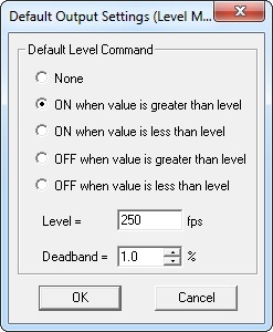
Level - the rate- or interval-scaled count (or timer) value used for the action. Notice also the 4-character Engineering Units text field entered in the rate or interval scaling wizard are shown to the right of the value.Deadband - the percentage of the Level value in which there will be no CTRIO output change. This is used to prevent CTRIO output chattering (rapidly toggling OFF/ON) in case the rate- or interval-scaled count (or timer) value is fluctuating too rapidly. Thus, for example, if the Default Level Command was set to "ON when value is greater than level", the Level value is 500 and Deadband is set to 10.0% then when the scaled value reaches 500, the output will come ON. But if at that point the scaled value begins to go lower than 500, it will not turn back OFF until the value reaches 450 (500 minus 10.0%).
Discrete Output For Pulse Output Function
Discrete on Pulse Out x/x is available on Out0, Out1, Out2 & Out3 but only if one output pair (i.e. Out0/Out1 or Out2/Out3) is configured for Pulse Output. This function allows the output to be used in conjunction with the other pulse output pair and utilized by a previously defined discrete output table. This works just like the Discrete Output For Input Function above with the exception that the Preset or Level buttons are not supported.
Pulse Output
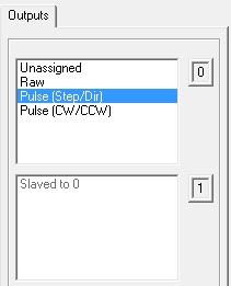
Pulse (Step/Dir) / Pulse (CW/CCW) is available on Out0/Out1 & Out2/Out3 pairs. This function allows two outputs to be used together where the first one is a pulse output and the second one is a direction output bit (step/dir) or where the first one generates pulses for clockwise motion and the second one generates pulses for counter-clockwise motion (cw/ccw). This function is used in conjunction with previously defined pulse profiles and/or CTRIO Do-more instructions.
Previously defined pulse profiles and CTRIO Do-more instructions that are used with pulse output:
-
CTAXCFG (CTRIO2 Axis Configuration) - defines a pulse output behavior with the luxury of not having to use a previously defined pulse profile.
-
CTAXDYNP (CTRIO2 Axis Run Dynamic Position Mode) - uses a pulse output which was previously defined by the CTAXCFGinstruction for asymmetrical linear trapezoidal movement where any number of positions can be specified on-the-fly
-
CTAXDYNV (CTRIO2 Axis Run Dynamic Velocity Mode) - uses a pulse output which was previously defined by the CTAXCFG instruction for asymmetrical linear trapezoidal movement where any number of velocities can be specified on-the-fly
-
CTAXJOG (CTRIO2 Axis Jog Mode) - uses a pulse output which was previously defined by the CTAXCFG instruction for manual asymmetrical linear trapezoidal movement forward or backward
-
CTAXLIMT (CTRIO2 Axis Run Trapezoid w/Limits) - uses a pulse output which was previously defined by the CTAXCFG instruction for asymmetrical linear trapezoidal movement to specified physical limits or positions
-
CTAXTRAP (CTRIO2 Axis Run Trapezoid) - uses a pulse output which was previously defined by the CTAXCFG instruction for asymmetrical linear trapezoidal movement to specified target position
-
CTDYNPOS (CTRIO Run Dynamic Position Mode) - uses a pulse output and one of the following previously defined pulse profiles:
-
Dynamic Position - symmetrical linear trapezoidal movement where any number of positions can be specified on-the-fly
-
Dynamic Position Plus - (CTRIO2 only) asymmetrical linear trapezoidal movement where any number of positions can be specified on-the-fly with the additional option of using a quadrature encoder attached to the CTRIO2 input channel to provide the position
-
CTDYNVEL (CTRIO Run Dynamic Velocity Mode) - uses a pulse output and the following previously defined pulse profile:
-
Dynamic Velocity - asymmetrical linear trapezoidal movement where any number of velocities can be specified on-the-fly
-
CTRUNPOS (CTRIO Run Position Mode) - uses a pulse output and one of the following previously defined pulse profiles:
-
Trapezoid - asymmetrical linear trapezoidal movement to a total number of pulses
-
Symmetrical S-Curve - symmetrical S-shaped movement to a total number of pulses
-
Home Search - movement profile used to find a home position utilizing a CTRIO2 input
-
Free Form - custom movement profile allowing any number of steps each having a number of pulses to be output at a specified frequency
-
Trapezoid Plus - (CTRIO2 only) asymmetrical linear trapezoidal movement to a run-time-provided position with the additional option of using a quadrature encoder attached to the CTRIO2 input channel to provide the position
-
Trapezoid w/Limits - (CTRIO2 only) asymmetrical linear trapezoidal movement to a deceleration trigger (a CTRIO2 input) and then to a stop trigger (a position or a CTRIO2 input) with the additional option of using a quadrature encoder attached to the CTRIO2 input channel to provide the position.
-
CTRUNVEL (CTRIO Run Velocity Mode) - uses a pulse output with the luxury of not having to use a previously define pulse profile to specified physical limits or positions
See Also:
Module Configuration for H2-CTRIO, H2-CTRIO2 or T1H-CTRIO
CTRIO / CTRIO2 Instructions
CTDYNPOS - CTRIO Run Dynamic Position Mode
CTDYNVEL
- CTRIO Run Dynamic Velocity Mode
CTPLSADD - CTRIO Add Entry to PLS
CTPLSEDT
- CTRIO Edit PLS Entry
CTREGWR -
CTRIO Write Register
CTRUNPOS - CTRIO Run Position Mode
CTRUNVEL
- CTRIO Run Velocity Mode
CTTBLADD - CTRIO Add Entry to Preset Table
CTTBLEDT
- CTRIO Edit Preset Table Entry
CTRIO2 Only Instructions
CTAXCFG - CTRIO2
Axis Configuration
CTAXDYNP - CTRIO2 Axis Run Dynamic Position Mode
CTAXDYNV
- CTRIO2 Axis Run Dynamic Velocity Mode
CTAXTRAP - CTRIO2 Axis Run Trapezoid
CTAXLIMT
- CTRIO2 Axis Run Trapezoid w/ Limits
CTAXJOG - CTRIO2 Axis Jog Mode
Related Topics: