Topic: DMD0308

Monitor CTRIO Module
The Main Display
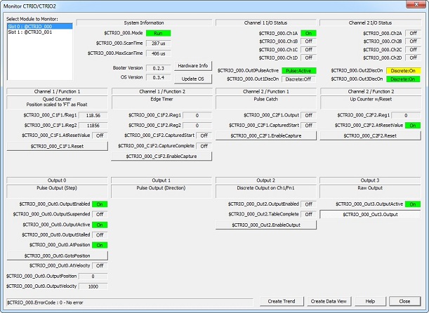
The Monitor CTRIO Module view is used to monitor the CTRIO2 (and CTRIO) modules installed in your system, and optionally change the values of their R/W structure bits. Multiple Monitor CTRIO Module views can be open at the same time, each monitoring the same or different CTRIOs. The display is dynamic in that the information displayed reflects the unique configuration of the CTRIO module selected.
Floating - the Monitor CTRIO Module view is a floatable window that cannot be resized.
To pull up a new Monitor CTRIO Module view select PLC --> Monitor CTRIO Module menu option.
The dialog is split into 3 rows each taking up approximately 1/3 of the vertical height and a single bottom line:
-
First row:
-
Select Module to Monitor (Click here for help on Select Module to Monitor)
-
System Information (Click here for help on System Information)
-
Hardware Info (button) (Click here for help on Hardware Info)
-
Update OS (button) (Click here for help on Updating OS)
-
Channel 1 I/O Status (Click here for help on Channel I/O Status)
-
Channel 2 I/O Status (Click here for help on Channel I/O Status)
-
Second row:
-
Channel 1 / Function 1 (Click here for help on Channel Functions)
-
Channel 1 / Function 2 (Click here for help on Channel Functions)
-
Channel 2 / Function 1 (Click here for help on Channel Functions)
-
Channel 2 / Function 2 (Click here for help on Channel Functions)
-
Third row:
-
Output 0 (Click here for help on Outputs)
-
Output 1 (Click here for help on Outputs)
-
Output 2 (Click here for help on Outputs)
-
Output 3 (Click here for help on Outputs)
-
Very bottom line:
-
Error Status (Click here for help on Error Status)
-
Create Trend (button) (Click here for help on Creating a Trend)
-
Create Data View (button) (Click here for help on Creating a Data View)
Select Module to Monitor
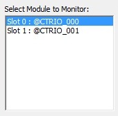
The Select Module to Monitor window is where the particular CTRIO module to monitor is selected. By default, when the Monitor CTRIO Module view comes up, it will select the first module in the window. To change modules, simply click on that module and the rest of the display will change accordingly.
System Information
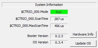
The System Information section is where the CTRIO's various system parameters are displayed. This dialog allows the reading of the CTRIO hardware information and the updating of the CTRIO's operating system.
The CTRIO structure member, .Mode, shows whether the CTRIO is in Run (green background) mode or Program (yellow background) mode. The mode information is stored as a number (1 = Program Mode or 2 = Run Mode) in the module and can be seen in the Data View.
The CTRIO structure member, .ScanTime, shows the current scan time of the CTRIO, so this number fluctuates.
The CTRIO structure member, .MaxScanTime, is the maximum CTRIO scan time in microseconds.
The Booter Version and OS Version shows the version of these sections of code in the CTRIO.
Hardware Info
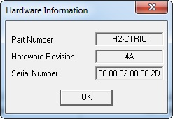
The <Hardware Info> button yields the Part Number, Hardware Revision and Serial Number of the CTRIO selected.
Update OS
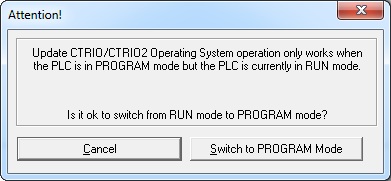
To update the CTRIO firmware, press the <Update OS> button. Updating the CTRIO OS will not destroy the configuration; it will leave it completely intact. If the Do-more PLC is in the program mode, an Attention! dialog will come up allowing the choices to cancel the update or switch the PLC into program mode so the update can continue. If the <Cancel> button is pressed the message will disappear and return to the Monitor CTRIO Module main screen.
If the <Switch to PROGRAM Mode> button is pressed a dialog will pop up in the Do-more Designer\Bin\Images CTRIO folder allowing the selecting of the proper firmware file for update.
Next a confirmation dialog will pop up. If all looks OK, then the <OK> button is pressed.
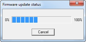
When the confirmation is OK'd, then a status window will show the progress of the CTRIO OS update. Once the status reaches 100%, the CTRIO will reboot itself and if the Do-more PLC was previously in Run mode, a dialog will appear asking if it should switch back to the Run mode. Once this is done the Monitor CTRIO Module main screen is once again displayed.
Channel I/O Status
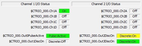
This section gives the general status of all the CTRIO's inputs (Ch1A, Ch1B, Ch1C, Ch1D, Ch2A, Ch2B, Ch2C & Ch2D) and outputs (Out0, Out1, Out2 & Out3). The CTRIO structure members that are pertinent to the output configurations will be shown (e.g. .Out0PulseActive will be shown if Out0 is configured for Pulse Step/Dir or Pulse CW/CCW, but .Out0DiscOn if it is configured as a Discrete Out For Input Function.
No color means inactive or OFF.
A green color means active or ON.
A yellow color means the CTRIO "wants" to turn the physical output ON, but cannot because it has not been enabled by a manual setting of the .EnableOutput bit.
Channel Functions
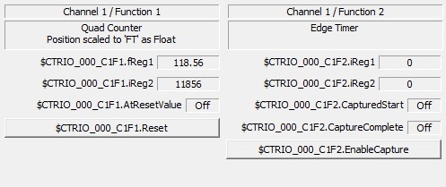
This section shows the status of all the channel functions configured (Ch1/Fn1, Ch1/Fn2, Ch2/Fn1 & Ch2/Fn2). The CTRIO structure members that are pertinent to the input function configurations will be shown (e.g. notice in the picture below that Channel 1 / Function 1 is configured as a quad counter with floating-point position scaling, thus register 1 floating-point structure member is shown first (.fReg1) and register 2 shows the raw count (.iReg2), whereas Channel 1/ Function 2 is configured as an edge timer with no scaling and thus register 1 & 2 are both integer time values (.iReg1, iReg2)). Also the feedback bits are given that are necessary careabouts for an edge timer function (.CapturedStart, .CaptureComplete).
Additionally, if there are any R/W CTRIO structure members that can be manually controlled, they will appear as buttons that can be pressed in (ON) or left out (OFF). The problem here is if these members are being controlled from the ladder logic already, then pressing these buttons may do no good since the ladder logic can write many times faster than a manual button press.
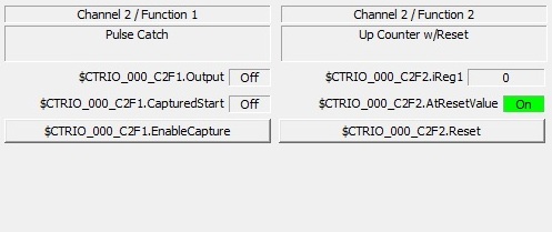
Notice in the picture below showing Channel 2's Functions 1 & 2, the appropriate read-only CTRIO structure members are shown for Function 1's pulse catch (.Output, .CapturedStart) as well as a manual button to execute it (.EnableCapture). Notice for Function 2, which is a simple unscaled up counter (with an input configured for a hardware reset function) also shows the careabouts for this function; the raw count (.iReg1) and the bit showing if the raw count is at reset value or not (.AtResetValue). It also has a button for the software reset (.Reset).
Outputs
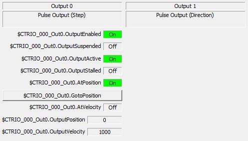
This section shows the status of all the output functions configured (Out0, Out1, Out2 & Out3). The CTRIO structure members that are pertinent to the output function configurations will be shown (e.g. notice in the picture below that Output 0 & 1 is configured as a pulse output (step & direction) thus all the structure members associated with this function are shown (.OutputEnabled, .OutputSuspended, .OutputActive, .OutputStalled, .AtPosition, .AtVelocity, .OutputPosition & .OutputVelocity). Not all of these are necessarily pertinent to a particular instruction or pulse profile that may be running on this output. Those are explained thoroughly in each CTRIO instruction that can use a pulse output.
Additionally, if there are any R/W CTRIO structure members that can be manually controlled, they will appear as buttons that can be pressed in (ON) or left out (OFF). The problem here is if these members are being controlled from the ladder logic already, then pressing these buttons may do no good since the ladder logic can write many times faster than a manual button press.
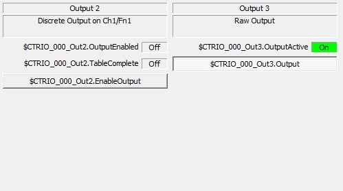
Notice in the picture below showing Output 2's configuration, the appropriate read-only CTRIO structure members are shown for the discrete output on channel 1 function 1 input (.OutputEnabled, .TableComplete) as well as a manual button to enable the output (.EnableOutput). Notice Output 3 is configured as a raw output and it is showing its output to be ON (.OutputActive) in green. The reason is the manual button (.Output) is pressed in (ON).
Error Status
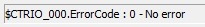
At the very bottom line on the far left is the error status bar. Here the last error code from the CTRIO module is displayed. The error codes are explained in full in the help for each of the Do-more CTRIO instructions.
Create Trend View for CTRIO
Since the Monitor CTRIO Module view shows only the pertinent CTRIO structure members for its input and output functions, it is the perfect place to automatically create trend views. This saves the user from having to create them by manually typing them in.
Pressing the <Create Trend> button pulls up the Create Trend View. This view lists all the CTRIO structure members being shown on the Monitor CTRIO Module display. They are sectioned off by module structure (e.g. $CTRIO_000), input functions ($CTRIO_000_C1F1, $CTRIO_000_C1F2, $CTRIO_000_C2F1 & $CTRIO_000_C2F2) and output functions (e.g. $CTRIO_Out0, $CTRIO_Out1, $CTRIO_Out2 & $CTRIO_Out3).
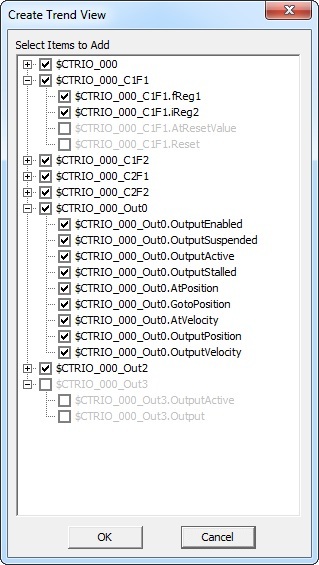
By default everything is checked, meaning the dialog will attempt to create a Trend View with all this data. Most of the time this is way too much data because only 5 panes can be created per Trend View. Thus, the reason for the check boxes.
The plus sign allows each group to be opened up to sub-members of that group. Unchecking the top group designator (e.g. $CTRIO_000_Out3 as shown in the pic at the right) will uncheck all its members (e.g. $CTRIO_000_Out3.OutputActive & $CTRIO_000_Out3.Output) and they will become gray.
Also, each individual member of a group can be unchecked.
Note: There is not a one-to-one correspondence between groups and Trend View panes because a group can have values and bits, and values and bits cannot be displayed on the same pane. Thus one group (e.g. $CTRIO_000_Out0) has both values (e.g. $CTRIO_000_Out0.OutputPosition & $CTRIO_000_Out0.OutputVelocity) and bits (e.g. $CTRIO_000_Out0.OutputEnabled, .$CTRIO_000_Out0.OutputSuspended, etc). Also some values in a single group (e.g. $CTRIO_000_C1F1) would not plot well together because one is a scaled value (e.g. $CTRIO_000_C1F1.fReg1) and one is raw (e.g. $CTRIO_000_C1F1.iReg2).
Thus, the best thing to do when creating Trend Views from the Monitor CTRIO Module display is to do the operation several times, selecting a different group each time and thus creating multiple Trend Views.
When all desired selections are made, pressing the <OK> button will create the Trend View.
Create Data View for CTRIO
Since the Monitor CTRIO Module view shows only the pertinent CTRIO structure members for its input and output functions, it is the perfect place to automatically create data views. This saves the user from having to create them by manually typing them in.
Pressing the <Create Data View> button pulls up the Create Data View. This view lists all the CTRIO structure members being shown on the Monitor CTRIO Module display. They are sectioned off by module structure (e.g. $CTRIO_000), input functions ($CTRIO_000_C1F1, $CTRIO_000_C1F2, $CTRIO_000_C2F1 & $CTRIO_000_C2F2) and output functions (e.g. $CTRIO_Out0, $CTRIO_Out1, $CTRIO_Out2 & $CTRIO_Out3).
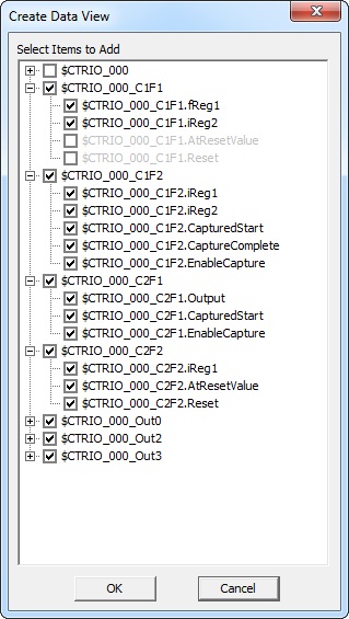
By default everything is checked, meaning the dialog will create a Data View with all this data.
The plus sign allows each group to be opened up to sub-members of that group. Unchecking the top group designator (e.g. $CTRIO_000 as shown in the pic at the right) will uncheck all its members and they will become grayed out.
Also, each individual member of a group can be unchecked (e.g. $CTRIO_000_C1F1.AtResetValue & $CTRIO_000_C1F1.Reset).
When all desired selections are made, pressing the <OK> button will create the Data View.