Topic: DMD0377

BRX On-board High Speed I/O
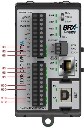
On BRX PLCs with 24 VDC inputs, the first 10 of the on-board inputs (X0 - X9) - if it has that many are High-Speed inputs. These inputs are capable of working with 250 kHz inputs. These inputs are typically used for very fast input signals from external devices like encoders.
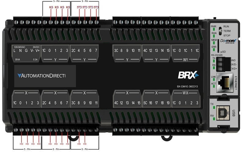
All BRX PLCs with 24 VDC outputs have High-Speed outputs. Only the first 1/2 of the on-board outputs are High-Speed (Y0 - Y1 on BX-DM1x-10's), (Y0 - Y3 on BX-DM1x-18's), and (Y0 - Y7 on BX-DM1x-36's), the remaining outputs are standard speed. These High-Speed outputs are capable of generating pulse trains in the range of 10 Hz to 250 kHz outputs @ 1m; (maximum velocity is reduced to 100 kHz @10m or with a ZipLink .5m cable only). These very fast output signals are typically used for external devices like stepper motor drives.
|
BX-DM1x-10ED1, BX-DM1x-10ED13, BX-DM1x-10ED2, BX-DM1-10ED23
(BX-DM1x-10ER, BX-DM1x-10ER3 only have High-Speed Inputs)
|
BX-DM1x-18ED1, BX-DM1x-18ED13, BX-DM1x-18ED2, BX-DM1-18ED23
(BX-DM1x-18ER, BX-DM1x-18ER3 only have High-Speed Inputs) 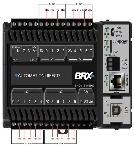
|
BX-DM1x-36ED1, BX-DM1x-36ED13, BX-DM1x-36ED2, BX-DM1-36ED23
(BX-DM1x-36ER, BX-DM1x-36ER3 only have High-Speed Inputs)
Input Functions (Counter / Timer / Pulse Catch)
The BRX on-board High-Speed inputs can be selected for use as high speed Counters that will count input pulses up to 250kHz, or as high speed Timers that will measure the amount of time between successive input pulses at frequencies up to 250 kHz, or generate an output signal that can be seen by the PLC scan in response to input pulses that are too fast to reliably be seen otherwise (Pulse Catch).
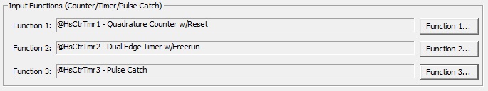
Function 1... / Function 2... / Function 3...: a BRX CPU can have up to three Counter / Timer functions defined. Clicking one of theses buttons will open a dialog where Counter or Timer function is selected, the function is given a name, and the number of physical inputs required by that function are selected. A full discussion of how to configure and use these functions can be found at BRX Timer / Counter Functions.
Axis / Pulse Outputs
The BRX on-board High-Speed outputs can be selected for use as pulse outputs which are typically used to send pulse trains to stepper motors or servo motors at a frequency up to 250 kHz.
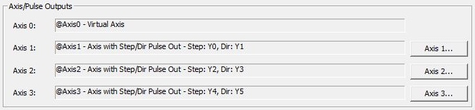
A BRX CPU can have up to four Axes. Axis 0 is always virtual, meaning it can be used in the program like the other Axes but can never be bound to physical outputs.
Axis 1... / Axis 2... / Axis 3...: Axis 1, Axis 2 and Axis 3 can remain virtual or be bound to physical outputs. Clicking one of theses buttons will open a dialog where the Axis is given a name, the type of outputs required by that Axis, and which physical outputs will be used by that Axis. A full discussion of the BRX Axis and how it uses the pulse outputs can be found at BRX Axis / Pulse Outputs.
Once an Axis is configured you will use the following instructions to set the runtime configuration of the Axis and to make the Axis move:
AXSETPROP - Axis Set Properties
AXRSTFAULT - Reset Axis Limit Fault
AXHOME - Axis Perform Home Search
AXPOSSCRV - Axis Move to Position Using S-Curve
AXPOSTRAP - Axis Move to Position Using Trapezoid
AXVEL - Axis Set Velocity Mode
AXGEAR - Axis Electronic Gearing
AXFOLLOW - Axis Position Following with Offset
AXCAM - Axis Electronic Camming
PWM (Pulse Width Modulated) Outputs
The BRX on-board High-Speed outputs can be used to generate a carrier frequency then vary the width of the pulses that are generated at that frequency.
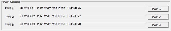
PWM 1... / PWM 2... / PWM 3...: a BRX CPU can have up to 3 PWM Outputs. Clicking one of these buttons will open a dialog where the PWM Output is given an name and the physical output that will be used by that PWM is selected. A full discussion of how to configure and use these outputs can be found at BRX Pulse Width Modulated Outputs.
Each time a PWM Output is created an associated structure is automatically created. The runtime configuration of the PWM Output is configured by writing to those structure members. As of Do-more Designer v2.5, the PWMOUT - Pulse Width Modulated Output instruction can be used to control a BRX PWM Output instead of manually populating the structure fields.
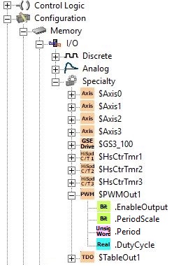
Table Driven Outputs
The BRX on-board High-Speed outputs can be selected to use the count values of one of the module's High-Speed inputs along with tables of preset values to turn the module's High-Speed outputs ON and OFF .
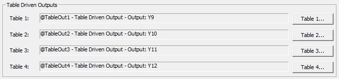
Table 1... / Table 2... / Table 3... / Table 4... - a BRX CPU can have up to four Table Driven Outputs. Clicking one of the buttons will open a dialog where that Table Drive Output is given a name and the physical output used by that table is selected. A full discussion of how to configure and use these outputs can be found at BRX Table Driven Outputs.
After the High-Speed I/O discrete output has been configured for use as a Table Driven Output, it is controlled using a Preset Table or a PLS Table.
TDOPLS - Load Programmable Limit Switch Table for Table Driven Output
TDOPRESET - Load Preset Table for Table Driven Output
TDODECONFIG - Deconfigure Table Driven Output
See Also:
BX-HSIO1 / BX-HSIO2 High-Speed I/O Modules