Topic: DMD0302

PACKETOUT - Output Data to Packet Device
The Output Data to Packet Device (PACKETOUT) instruction uses a UDP Connection device to send packets of up to 1024 bytes of data from a String or up to 1536 bytes of a numeric data block out through the CPU's on-board Ethernet port to a UDP Server.
If the data to send is ASCII text then use the Print to String (STRPRINT) instruction to build up the contents of the String that will be sent to the specified device.
If the data is binary (just Bytes of data) use the Put Bytes Into a String (STRPUTB) to store the Byte data in the String.
The Clear Device (DEVCLEAR) instruction can be used to delete any existing packets in the UDP Connection's output buffer.
Parameters:
Note: Use the F9 key or click the 'three dot box' at the right edge of the parameter field to open the Default Element Selection Tool (the Element Picker or the Element Browser) or use the Down-Arrow key (Auto-Complete) on any parameter field to see a complete list of the memory locations that are valid for that parameter of the instruction.
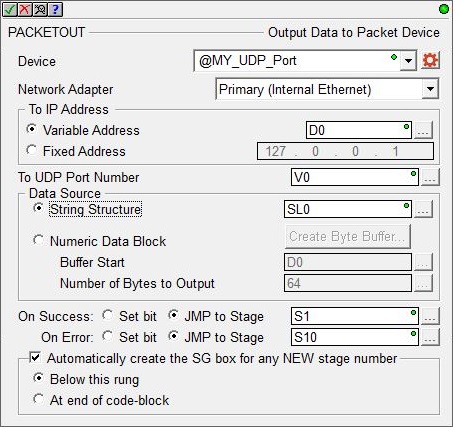
Device specifies which of the UDP Connection devices to use to send
the data from the specified String or numeric memory block.
Device selects one of the existing UDP Connections. Click the gear symbol at the right end of the Device field to open the System Configuration page for that UDP Connection Device.
double-click to create device indicates that there are no UDP Connections that have been configured to perform this instruction. Selecting this option will invoke the New Device configuration page of the System Configuration dialog where a UDP Connection device can be created.
Network Adapter: because this instruction can use Ethernet broadcasts to send packets, you can select which of the Ethernet ports to send the packets through:
Default means the TCP stack will route the packets to the first Ethernet port that can process the packet; on CPUs without a Secondary port (BX-P-ECOMEX) this will always be the on-board port. This is also the proper selection for backwards compatibility with previous Do-more Technology versions and with H2-DM1E, T1H-DM1E, and BX-DM1 CPUs because they have no provision for a Secondary Ethernet port.
Primary (Internal Ethernet) will send packets through the on-board Ethernet port of the Do-more CPU.
Secondary (BRX ECOMEX) will send packets through the BRX CPU's secondary Ethernet port (BX-P-ECOMEX).
To IP Address selects one of the following two options of setting the IP address of the Ethernet device to send the UDP packet to.
-
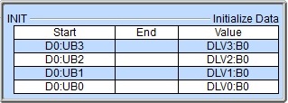
Select the Variable Address option to specify a numeric memory location that holds an IP Address value. This is typically the IP Address from a previously executed Input Data from Packet Device (PACKETIN) instruction. This can be any readable DWord numeric location. This allows the IP Address to be changed at runtime. Each octet of the IP Address is stored in one byte of the Variable Address location. In the example below the Initialize Data instruction will use the :UB operator to place the 4 octet values of IP Address 192.168.26.71 into the 4 Bytes of the DWord location D0 in the proper order.
-
Select Fixed Address to enter the IP address values manually. Each of the four octets of the IP Address can be any constant value from 0 to 255. Opening the Default Element Selection Tool (F9) on this field will open the IP Address Lookup utility that can find the IP Address for a given name.
To UDP Port Number is the UDP Port Number to send the UDP packet to. This could be the value from a previously executed Input Data from Packet Device (PACKETIN instruction. This value is a decimal value in the range of 0 - 65535.
Data Source selects where the data to send to the UDP Connection is currently stored. The option chosen will depend on the type of data that is to be sent. If the data is ASCII text the appropriate location is a String Structure. If the data is binary (simply bytes of data) the appropriate choice is a numeric block of bytes.
String Structure is a String
where the data to send to the UDP Connection is stored. This can be any of the system-defined Short Strings (SS, up to 64 bytes), or system-defined Long Strings (SL, up to 256 bytes), or a user-defined String, which can be a maximum of 1,024 bytes.
Numeric Data Block is the numeric data block where the data to send to the Packet Device is stored. The maximum size of the data block that can be sent in a single packet is 1536 bytes (768 Words, 384 DWords).
Click the Create Byte Buffer... button
to open the following dialog where the programmer can create a new data
block of BYTEs to store the data.
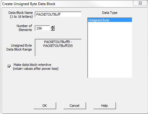
The Data Block Name (1 to 16 letters) must be unique, and consist of 1 to 16 characters (A-Z, a-z; no numbers, no spaces). The default name PACKETOUTBuff can be changed if desired.
Number of Elements is the size of the data block to create. Data blocks must be created on a DWord (4-byte) boundary. The maximum number of Bytes that can be sent in a single packet is 1024.
Unsigned Byte Data Block Range displays the first and last element of the block that will be created based on the current entries for Data Block Name and Number of Elements.
Data Type means the data block will consist of Unsigned Bytes.
Make data block retentive (retain values after power loss) means that a data block marked as retentive will hold its state through a power cycle or a Program-to-Run mode transition. The status of memory NOT marked as retentive will be cleared at power up and during a Program-to-Run mode transition.
Buffer Start is the offset in an existing
numeric data block where the data begins.
Number of Bytes to Output specifies a location that contains the number of bytes to send. The maximum number of bytes that can be sent in a single packet is 1536.
The On Success and On Error parameters specify what action to perform when this instruction completes. You do not have to use the same type of selection for both On Success and On Error.
If the Set Bit selection is used for either On Success or On Error, the specified BIT location will be SET OFF when the instruction is first enabled and will remain OFF until the instruction completes. Once complete, the appropriate Success or Error bit location ON. The specified Bit location is enabled with a SET (Latch) operation meaning that it will remain ON even if the input logic for the instruction goes OFF.
If the JMP to Stage selection is used for either On Success or On Error the target Stage must be in the same Program code-block as this instruction, you cannot specify a target Stage that exists in a different Program code-block. When the operation finishes, the target Stage will be enabled the same way as a standalone Jump to Stage (JMP) instruction would do it. The JMP to Stage option will only be available if this instruction is placed in a Program code-block.
On Success selects which of the following actions to perform if the operation is successful:
- Enable SET Bit then specify any writable bit location.
- Enable JMP to Stage then specify any
Stage number from S0 to S127 in the current Program code-block.
On Error selects which of
the following actions to perform if the operation is unsuccessful:
- Enable SET Bit then specify writable bit location.
- Enable JMP to Stage then specify any Stage number from S0 to S127 in the current Program code-block.
If either the On Success or On Error selections are set to JMP to Stage, Automatically create the SG box for any NEW stage number will be enabled which will automatically create any target stage that does not already exist.
- Below this rung will create the new target stage on a new rung following this instruction.
- At end of code-block will create the new target stage as the last rung of this Program.
Packet Device Structure Fields:
An Input Packet from Packet Device instruction will reference a Packet Device![]() A pre-configured device that is capable of communicating via UDP/IP protocol through the on-board Ethernet port of a Do-more CPU. .
A pre-configured device that is capable of communicating via UDP/IP protocol through the on-board Ethernet port of a Do-more CPU. .
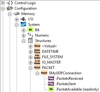
Each Packet device has an associated structure which contains the following member fields:
.PacketsReceived (Read / write) is a 16-bit Unsigned value that shows the number of packets that have been successfully retrieved from the UDP Connection's input buffer.
.PacketsSent (Read / write) is a 16-bit Unsigned value that shows the total number of packets that have been successfully sent from the UDP Connection's output buffer.
.PacketAvailable (Read-only) is a Bit that will be ON any time there is at least one packet in the UDP Connection's input buffer.
Status Display:
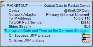
The red triangle in the upper left corner of the status display indicates this is a Fully Asynchronous instruction.
The gray triangle at the right end of the input leg indicates the input is edge-triggered, meaning this instruction will execute each time the input logic transitions from OFF to ON.
The Status display for the String or Numeric Block will only display as many of the characters of the destination location as will fit within the borders of the instruction, typically this is about 50 characters.
See Also:
PACKETIN - Input Data from Packet Device
PACKETOUT - Output Data to Packet Device
UDP Connection Device Configuration
Related Topics:
STREAMIN - Stream In Data from Device
STREAMOUT - Stream Out Data to Device
Example Using Stages:
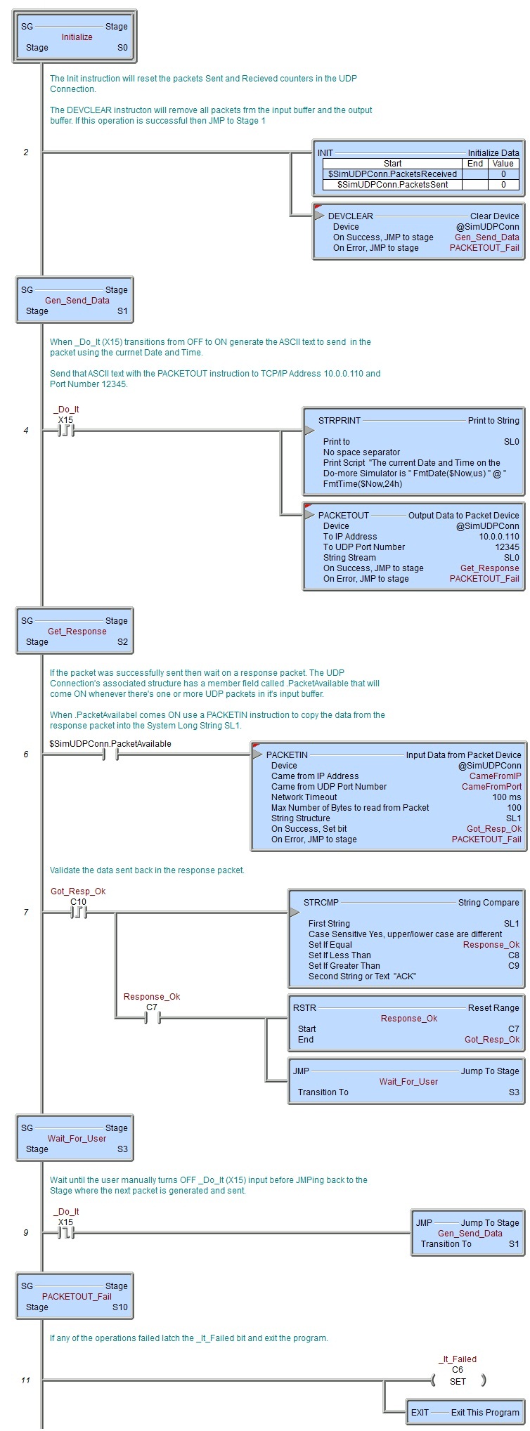
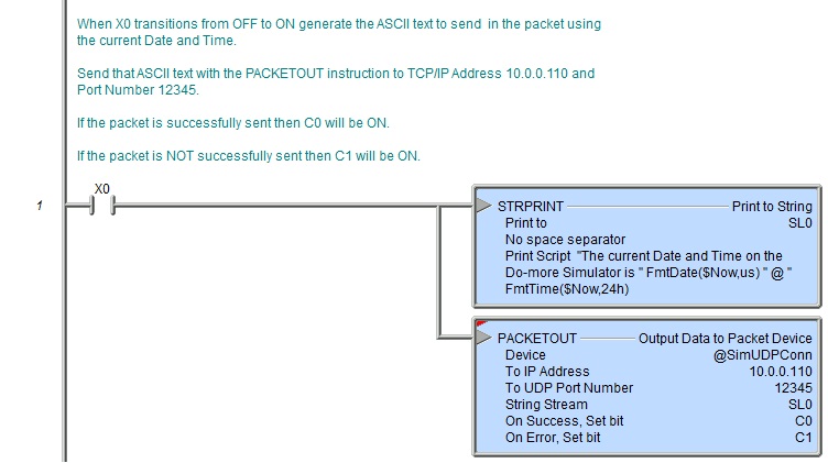
Rung Example: