Topic: DMD0495

MSREGRD - Modbus I/O Scanner Register Read
The Modbus I/O Scanner Register Read (MSREGRD) instruction uses a Modbus I/O Scanner Device to send additional Modbus Read operations to its target Modbus Server. The Scanner Device's configuration contains a series of Modbus Reads and Writes that are continually executed; this instruction allows event-based Reads to be interleaved into the Scanner Device's normal processing. Note: this instruction is intended to read register locations that are NOT already being read by the Scanner Device.
If the Scanner Device was created using a profile that contains Register definitions, that profile will be automatically opened to allow those Register locations to be selected by this instruction.
Parameters:
Note: Use the F9 key or click the 'three dot box' at the right edge of the parameter field to open the Default Element Selection Tool (the Element Picker or the Element Browser) or use the Down-Arrow key (Auto-Complete) on any parameter field to see a complete list of the memory locations that are valid for that parameter of the instruction.
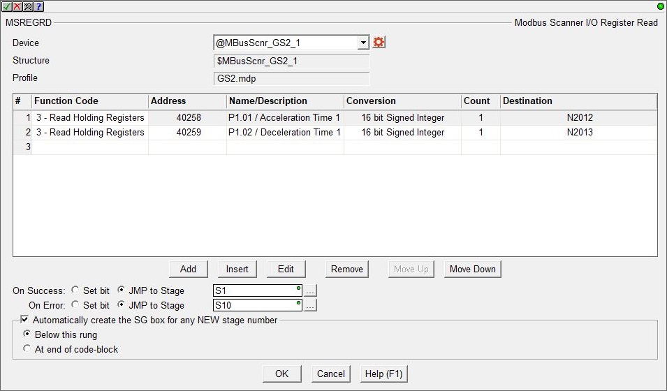
Device selects which of the configured Scanner Devices to use. Click the gear symbol at the right of the selection to open the Modbus I/O Scanner Configuration where a new Scanner Device can be created. Structure is the name of the Scanner Device's associated structure. Profile is the name of the profile used to create the Scanner Device (if applicable).
The center section contains the table of individual Modbus Read operations that will be performed each time this instruction is executed. The buttons below the table are used to manage the rows in the table: Add creates a new row after the currently selected row and opens the row editor. Edit opens the row editor to change the currently selected row. Insert inserts an empty row before the currently selected row and opens the row editor. Remove removes the currently selected row. Move Up / Move Down moves the currently selected row up one row or down one row in the table respectively.
To open the row editor, double-click on the row, or highlight a row then click the Add, Edit or Insert button.
After selecting the command and entering the parameters, use the buttons at the bottom of the dialog as follows: Save will commit any changes that were made to the command and close the row editor. Save / Next will commit any changes that were made to the command and begin editing the existing command entry in the next row. Save / Insert will commit any changes that were made to the command and create a new command entry below the row you just saved. Cancel will close the row editor without saving any changes that have been made.
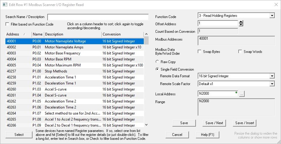
If the Scanner Device was created using a Profile, the left side of the dialog will display a list of any Register definitions that are part of that profile. Note: if the Scanner Device was not created with a profile, or the profile does not have any additional Register definitions, this list will be empty. Documenting Registers in User Profiles is done in the Device Profile section of the Modbus I/O Scanner Configuration dialog.
If the List of Registers is long, the Search Name / Description field can help find specific Register definitions in the list; as you enter text in the field the dialog will filter the list of Register definitions to contain only items that match the text in either the Name field or the Description field.
If Filter based on Function Code is enabled, the list will only contain Register definitions that are appropriate for use with the current selected Function Code.
Click Select (or double-click on the Register in the list) to copy that Register definition's information into their appropriate data fields.
Function Code selects the Modbus Function code the Scanner Device will use to read from the server. There are four supported Modbus Read Function Codes: 1 - Read Coils, 2 - Read Discrete Inputs, 3 - Read Holding Registers, and 4 - Read Input Registers.
Offset Address is the location in the server where the data resides.
Count (if Raw Copy Selected) / Count Based on Conversion (if Single Field Conversion is selected) is the number of successive memory locations to Read. The maximum number of locations is limited to 16). If Single Field Conversion is selected the limit is fixed at 1.
The Modbus Addresses field will display the Modbus address range that will be read based on the Function Code + Offset + Count.
The Modbus Data Byte / Word Order selections allow the Bytes and / or Words of the Register value to be reordered because of a difference in the Endianness of the Modbus server.
Enable only Byte Swap to swap the Bytes in each Word of the Read request.
For example: ABCD EFGH --> CDAB GHEF
Enable only Word Swap to swap the successive Words in each DWord of the Read request.
For example: ABCD EFGH --> (swap words) --> EFGH ABCD
Enable both selections to swap the bytes in each Word and swap successive Words of the Read request, (this reverses the byte order of a DWord value).
For example: ABCD EFGH --> (swap words) --> EFGH ABCD --> (swap bytes) --> GHEF CDAB
If needed, the next selection is used to convert from the data format used in the Modbus server to the data format of selected Local Address.
-
Selecting Raw Copy will place each element of the Read request in the specified Local Address locations with no format conversion.
-
Selecting Single Field Conversion will convert the data from the format of the selected Remote Data Format to the format of the Local Addressbefore it is stored.
Remote Data Format specifies the format of the data in the Modbus server: 16-Bit Signed, 16-Bit Unsigned, 16-Bit BCD or 32-Bit Signed, 32-Bit BCD, 32-Bit Float (real).
If the Local Address if a Real memory (R) location, and the Remote Data Format is an integer with implied decimal points, the Remote Scale Factor:selects the number of implied decimal points: Default x1 (no implied decimal points), Implied by x 10 (one implied decimal point), Implied by x 100 (two implied decimal points), Implied by x 1000 (three implied decimal points).
Local Address: is the memory location in the PLC where the data for this field will be stored. The Range field will display the range of PLC address that will be used to stored the data based on the Word Count.
If all of the listed READ operations were completed successfully the On Success selection will be executed. Processing of the listed READ operations will stop after the first failure and the On Error condition will be executed.
The On Success and On Error parameters specify what action to perform when this instruction completes. You do not have to use the same type of selection for both On Success and On Error.
If the Set Bit selection is used for either On Success or On Error, the specified BIT location will be SET OFF when the instruction is first enabled and will remain OFF until the instruction completes. Once complete, the appropriate Success or Error bit location ON. The specified Bit location is enabled with a SET (Latch) operation meaning that it will remain ON even if the input logic for the instruction goes OFF.
If the JMP to Stage selection is used for either On Success or On Error the target Stage must be in the same Program code-block as this instruction, you cannot specify a target Stage that exists in a different Program code-block. When the operation finishes, the target Stage will be enabled the same way as a standalone Jump to Stage (JMP) instruction would do it. The JMP to Stage option will only be available if this instruction is placed in a Program code-block.
On Success selects which of the following actions to perform if the operation is successful:
- Enable SET Bit then specify any writable bit location.
- Enable JMP to Stage then specify any
Stage number from S0 to S127 in the current Program code-block.
On Error selects which of
the following actions to perform if the operation is unsuccessful:
- Enable SET Bit then specify writable bit location.
- Enable JMP to Stage then specify any Stage number from S0 to S127 in the current Program code-block.
If either the On Success or On Error selections are set to JMP to Stage, Automatically create the SG box for any NEW stage number will be enabled which will automatically create any target stage that does not already exist.
- Below this rung will create the new target stage on a new rung following this instruction.
- At end of code-block will create the new target stage as the last rung of this Program.
Status Display:
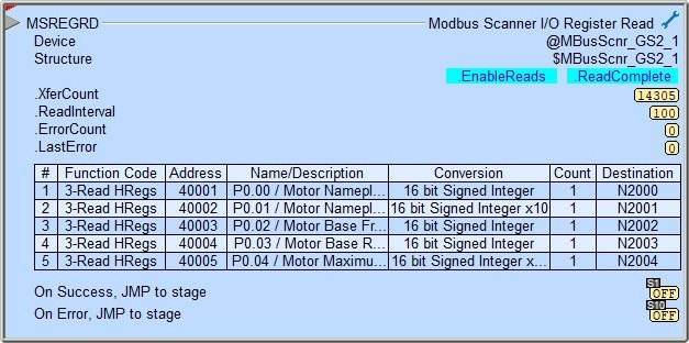
The red triangle in the upper left corner of the status display indicates this is a Fully Asynchronous instruction.
The gray triangle at the right end of the input leg indicates the input is edge-triggered, meaning this instruction will execute each time the input logic transitions from OFF to ON.
.EnableReads / .ReadComplete are the current state of these Bit values from the Scanner Device's associated structure.
.XferCount / .ReadInterval / .ErrorCount / .LastError are the current values of these numeric fields from Scanner Device's associated structure.
A detailed description of these Numeric and Bit fields and the possible error codes for LastError is available in the Modbus I/O Scanner Configuration help topic.
See Also:
MSREGRD - Modbus I/O Scanner Register Read
MSREGWR - Modbus I/O Scanner Register Write
Related Topics:
Modbus I/O Scanner Configuration