Topic: DMD0339

I/O System View
In Offline mode the I/O System View provides a static hierarchical representation of all of the I/O Masters and all of their I/O Modules in the current I/O Configuration. In Online mode it additionally provides detailed runtime Warning and Error information for all of the aforementioned components in the I/O Configuration. While the View is open, at 3 second intervals, the Error and Warning information is read from all the configured I/O Masters and the View is refreshed with the newly acquired data. The I/O System view can be opened by selecting PLC -> I/O System on the toolbar or by clicking the Open I/O System Window button on the System Status tab of the System Information dialog.
There two toolbar buttons that control how much information is displayed in the view:
If Show Only Errors and Warnings is enabled only the bases and I/O modules that are currently reporting an Error or a Warning will be listed. If disabled, all of the bases and I/O modules will be listed regardless of their current Error or Warning status.
Status will enable or disable the 3-second update to acquire the data for the I/O System View.
I/O System View uses a dockable / floatable window, the default location is docked to the left edge. The window is divided into two sections - using either a left / right layout or a top / bottom layout. Which of the two layouts is used depends on the shape of the frame:
Shapes that are wider than they are tall, or if they are docked on a horizontal edge will have a left / right pane layout.
Shapes that are taller than they are wide, or if they are docked on a vertical edge will have a top / bottom pane layout.
The Left (or Top) Pane
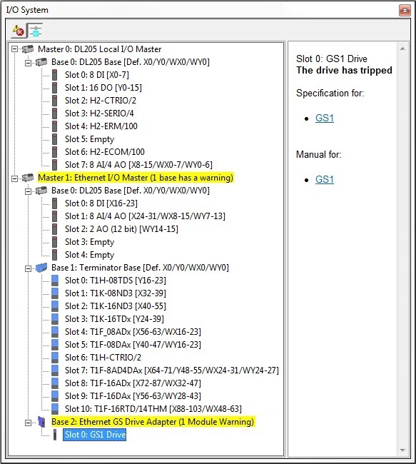
The Top (or Left) Pane contains a tree control that lists all of the I/O Masters in the system. For each I/O Master in the system it lists each Base controlled by that I/O Master. For each Base it lists each Slot with the type of I/O module (or the module's part number) and the I/O mapping information for that module.
The background color of the entries visually depicts which I/O Master, and / or Base, and / or module is currently returning Error or Warning information as follows:
-
 are entries with the normal background color are not
reporting any Errors or Warnings.
are entries with the normal background color are not
reporting any Errors or Warnings.
-
 are entries with the Yellow background color are reporting
Warnings.
are entries with the Yellow background color are reporting
Warnings.
-
 are entries with the Red background color are reporting
Errors.
are entries with the Red background color are reporting
Errors.
Highlighting an entry in the tree control will cause relevant information about that entry to be displayed in the Bottom (or Right) pane.
Right (or Bottom) Pane
The right (or bottom) pane contains hyper-links to online information for the selected item. Access to these online resources requires a functional connection to the Internet and a PDF viewer. In instances where multiple I/O Modules share a common Module ID, hyper-links for all of the possible modules will be listed.
Selecting one of the hyper-links in the Specification For: section will open the default web browser, which will then open a PDF file on Automationdirect's web site that displays the specification pages from the catalog. The Specification pages contain hardware requirements and wiring diagrams.
Selecting one of the hyper-links in the Manual For: section will open the default web browser, which will then open a page on Automationdirect's web site that contains links to the User Manual.
Right (or Bottom) Pane will also display data that is relevant to the item selected in the tree control of the Top (or Left) pane.
-
If the selected element is an I/O Master all of the Bases with I/O modules that are reporting Errors and / or Warnings will be listed
-
If the selected element is a Base all of the I/O modules in that base that are reporting Warnings will be listed. Hyper-links for the Specification and the User Manual for the device that is in the CPU-slot of that base will also be displayed.
Unable to communicate with the drive
The GS-EDRV100 is unable to serially communicate with the GS Drive.
Link sense triggered
The Link Monitor value stored in the Slave does not match the Link Monitor value being received in packets from the Ethernet I/O Master - this can happen if the I/O Master was power-cycled, or if the Slave is receiving packets from multiple Ethernet I/O Masters.
The drive has tripped
The GS Drive has tripped.
-
If the selected element is a Slot the Warnings that are being reported for the Slot will be listed along with a short description of the problem. Because some of the I/O modules use the same Module ID, hyper-links for the Specification and the User Manual for all of the possible I/O modules in that Slot will also be displayed.
I/O Configuration Changed - I/O Change Detected at Power Up
The Do-more CPU keeps a copy of the last known good I/O Configuration data stored in it's battery-backed memory. While the system is powered down, if an I/O module is removed, or an I/O module is added, or an existing I/O module is replaced with a different one, the collection of I/O modules will not match the collection that is in the battery-backed memory when the system is powered back on. The Do-more CPU will detect that the I/O modules in a PLC system changed during the power-cycle and will turn ON the System Information bit $InstIOChanged (ST134) - Module Configuration Changed at Power up.
Note: if the $BatteryLow (ST149) and the $InstIOChanged (ST134) are ON at the same time the Do-more CPU will power up in PROGRAM mode because the copy of the last known good copy of the I/O Configuration will NOT be present when the aforementioned comparison is done. This is a potentially serious condition that needs to be resolved before allowing the system to be put back into service. Refer to the Help section on Changing the CPU Battery to resolve the Battery Power Low indication.
Warning!: If you absolutely need for the CPU to go into RUN mode with the CPU in this low battery power condition then you will need to visually determine if the currently detected I/O Configuration is valid for the use by the project in the CPU then use either the Mode Switch on the front of the CPU or Do-more Designer's PLC Mode utility to manually place the CPU in RUN mode.
I/O Change Detected at Runtime
If the I/O System View is running when this I/O change is detected then the contents of the offline I/O System View will be out of synch with the current contents in the Do-more CPU. These two copies of the I/O configuration must be synchronized before Do-more Designer can continue. Refer to the contents of the I/O System View to determine the differences between offline and online I/O configurations. The following dialog is displayed to assist in getting them in synch:
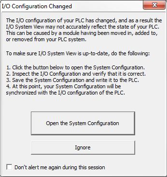
Open the System Configuration - click this button to open the System Configuration utility and display the I/O Configuration section which will read the current I/O configuration from the CPU then graphically show the detected I/O modules. At this point a decision needs to be made as to which copy of the I/O Configuration is correct.
If the currently detected I/O modules are correct - click the OK button to overwrite the offline copy of the I/O configuration with the I/O configuration data read from the CPU. Notice at this point that the 'Write to PLC' button is enabled which allows the updated version of the project to be downloaded to the CPU which will synchronize the PLCs contents with the offline project.
If the currently detected I/O modules are NOT correct - click the CANCEL button to leave the offline copy of the configuration intact, which will leave the offline copy out of sync with the online copy. At this point you should take whatever corrective action is required to get the I/O modules in the online configuration to match the configuration stored in the offline project.
Click the Ignore button to close the dialog and leave the project's copy of the configuration intact, which will leave the offline copy out of sync with the CPU's copy. At this point you should take whatever corrective action is required to get the I/O modules in the online configuration to match the configuration stored in the offline project.
Check the Don't alert me again during this session option to keep this alert dialog from being displayed any more while the current session of Do-more Designer is open.